TM 5-3810-289-34
(h) Remove drill, reamer assembly, hole
assembly and holddown adapter.
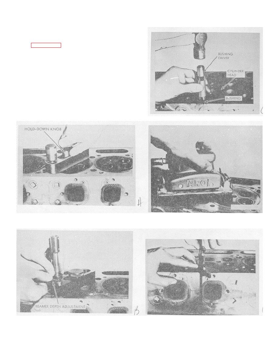
(i) Drive bushing into reamed hole with
driver, figure 3-126., Bushing should protrude about
0.003 to 0.005-in.
(j) If head is to be resurfaced, see (2) below.
If head is not to be resurfaced, file bushing flush with
head, using a wide flat mill file.
(2) Resurface cylinder head.
(a) Resurface head if it has been scratched,
etched or worn unevenly at point of contact with gasket
sealing areas. A head warped as much as 0.019 in. will
flatten out when tightened in position; there fore, it is not
necessary to resurface only because of warping. Also,
check erosion around water holes which could cause
failure of head gasket to seal. If eroded, install bushings
before resurfacing head.
Figure 3-126. Driving bushing into hole.
Figure 3-124. Inserting holdown knob into holder assembly.
Figure 3-127. Sand cylinder head.
Figure 3-125. Setting reamer depth.
Figure 3-128. Check cylinder head height.
3-46


