TM 5-3810-295-34
b.
Installation
(1) Refer to figure 2-6 and install front drumshaft assembly.
(2) Refer to TM 5-3810-295-12 and perform the following operation:
(a) Install front drum brake band.
(b) Open hydraulic reservoir shut-off valve. Bleed hydraulic line to the front drum assembly.
CAUTION
Be sure hydraulic fluid does not come into
2-14.
Reversing Shaft Assembly
a. Removal.
(1) Refer to TM 5-3810-295-12 and perform the following operations:
(a) Close hydraulic reservoir shut-off valve.
(b) Remove reversing shaft chain tension by adjusting the reversing shaft chain idler.
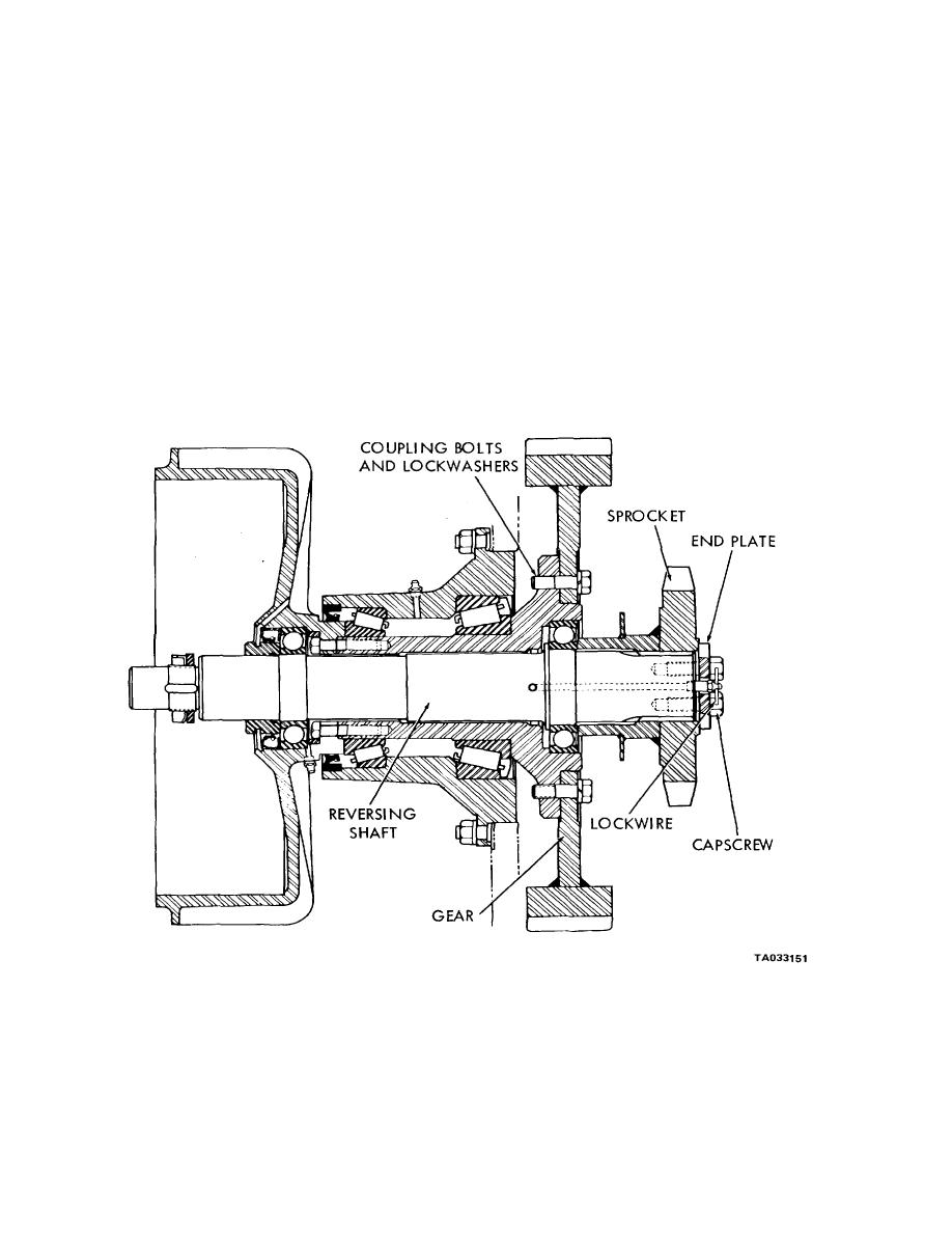
(c) Refer to figure 2-7. Remove the reversing shaft assembly. Lift chain from sprocket.
STEP 1. BREAK LOCKWIRE AND REMOVE END PLATE BY REMOVING
ATTACHING CAPSCREWS.
STEP 2. REMOVE SPROCKET .
STEP 3. REMOVE GEAR BY REMOVING ATTACHING COUPULNG BOLTS.
Figure 2- Reversing shaft assembly removal and installation (sheet 1 of 2).
2-27


