TM 5-3810-295-34
b. Lift covers (5) and (6) from housings (9) and
d. Remove filler cap (11) and filler tube (12).
e. Refer to figure 14-5. Remove screws (1) and (2),
remove gaskets (7).
c. Remove screws (8) and lift housings (9) from
and washers (3). Lift rocker lever assembly from the
the cylinder heads. Remove gaskets (10).
cylinder head.
1 Screw
9 Bushing
2 Screw
10 Intake Iever
3 Washer
11 Bracket
4 Bracket
12 Socket
5 Bushing
13 Nut
6 Exhaust lever
14 Adjusting screw
7 Bushing
15 Rocket shaft
8 Injector lever
16 Plug
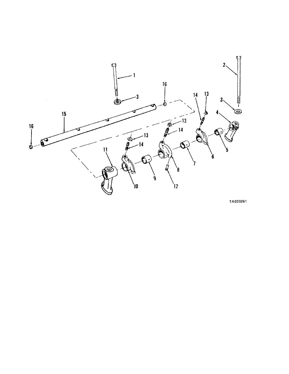
Figure 14-5. Rocker levers-exploded view
14-8. Disassembly
14-9. Cleaning, Inspection, Repair
Refer to figure 14-5.
a. Clean all metal parts in cleaning solvent, Federal
Specification P-D-680, or equivalent before inspecting.
NOTE
b. Check rocker lever for surface cracks or other
Tag rocker levers for correct position as
damage. Replace all defective parts.
removed.
c. Check rocker lever bushings for wear. Bushings
a. Remove brackets (4), bushings (5), exhaust levers
worn beyond 1.1915.- inches shall be replaced.
(6), bushings (7), injection levers (8), bushings (9), in-
d. Inspect intake and exhaust rocker lever
take levers (10), and brackets (11) from rocker shafts
crosshead
(15).
contact surface. Replace lever if a wedge shaped pat-
b. Remove adjusting screw locknuts (13) and adjust-
tern is evident.
ing screws (14) from rocker levers.
e. Check to assure the ball end of rocker lever
c. Remove cup plugs (16) from rocker shaft (15).
adjusting screws are true spheres. If worn flat on
bottom,
14-5


