TM 5-3810-295-34
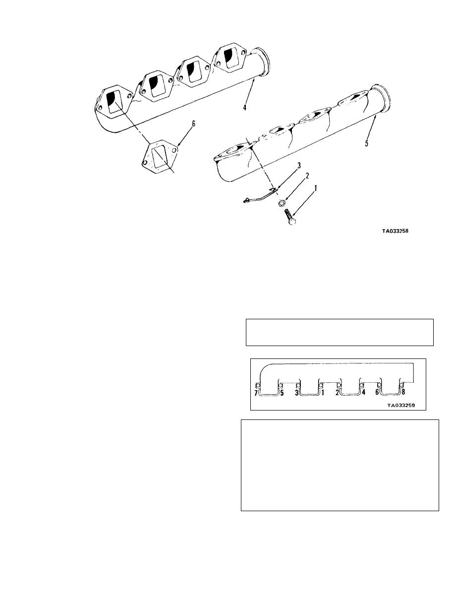
1 Screw
2 Washer
3 Lock plate
4 Manifold (right)
5 Manifold (left)
6 Gasket
Figure 14-2. Exhaust manifold assembly--exploded view.
14-5. Section II. Cleaning, Inspection and Repair
to 30-32 ft-lb (41-43 N . m) in 10 ft-lb (14 N . m)
a Clean all metal parts in cleaning solvent, Federal
increments in the sequence shown in figure 14-3.
Specification P-D-680, or equivalent before inspection.
b. Replace all gaskets.
c. Inspect manifolds for indications of cracks or
other damage. Check air hose for signs of wear, abra-
sion, or cuts. Replace all defective parts.
14-6. Reassembly and Installation
a. Refer to figure 14-2. Install gaskets (6) and as-
semble exhaust manifold (5) to engine. Lubricate
screws (1) with high temperature lubricant and secure
plates (3). Tighten screws to 45-50 ft-lb (61-68
Figure 14-3. Intake manifold tightening sequence.
N. m) in 15 ft-lb (20 N. m) increments. Install right
d. Install left side intake manifold (19) in the same
side manifold in the same manner.
manner as above.
b. Refer to figure 14-1. Position gasket (25), plate
e. Install gasket (14) and crossover connection (13)
(24) and gasket (20). Secure with screws (21), lock
and secure with screws (10), lock washers (11) and flat
washers (22) and flat washers (23).
washers (12). Install hose (2) and clamp (1) to the
c. Position right side manifold (18) on push rod
crossover connection. Install connection (8) and secure
cavity cover on the cylinder head. Install screws (15),
with screws (3), (4) and (5), lock washers (6) and flat
lock washers (16) and flat washers (17). Tighten screws
washers (7). Install pipe plug (9). Install other end of
hose (2) and secure with clamp (1).
14-3


