
TM 5-3810-305-23
0037
REMOVAL
NOTE
Tag all wire assemblies before disconnecting to aid in installation. Remove tags
following maintenance.
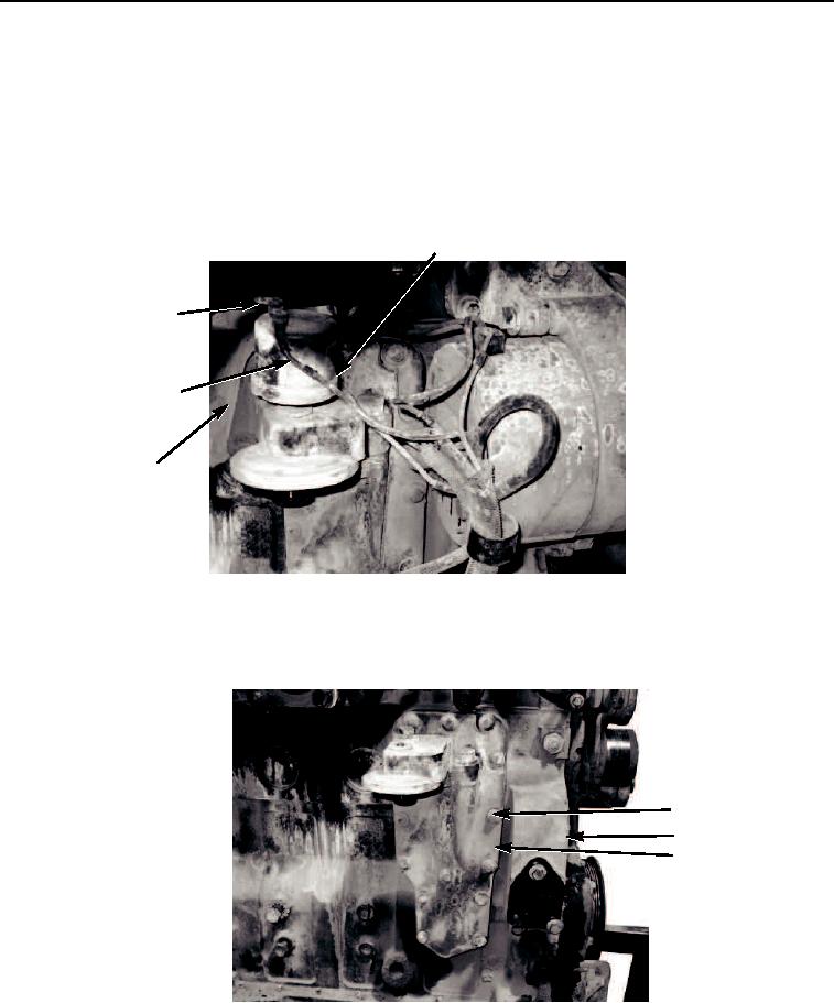
1.
Disconnect wires (Figure 1, Items 3 and 4) from oil pressure switch (Figure 1, Item 1) and remove oil pressure
switch from engine (Figure 1, Item 2).
1
4
3
2
M0212105
Figure 1.
Lube Oil Cooler Removal.
2.
Remove 14 capscrews (Figure 2, Item 1) and cover (Figure 2, Item 3) from engine (Figure 2, Item 2).
1
2
3
M0213105
Figure 2.
Lube Oil Cooler Removal.
3.
Remove cooler core (Figure 3, Item 3) and cooler core gasket (Figure 3, Item 2) from engine
(Figure 3, Item 1) and discard gasket.
03/15/2011Rel(1.8)root(maintwp)wpno(M00042)