
TM 5-3810-305-23
0051
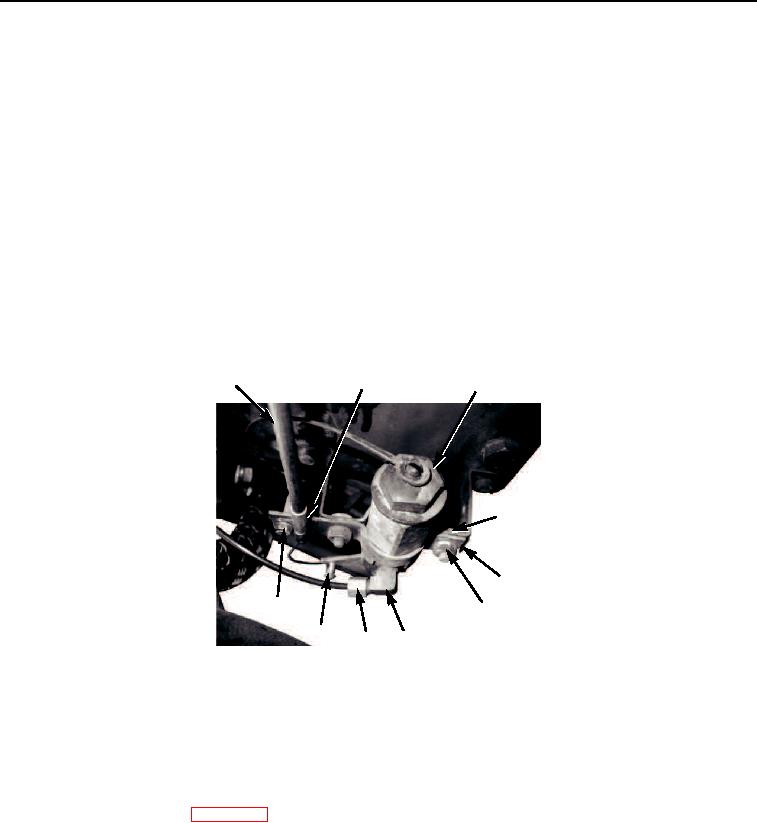
INSTALLATION - Continued
6.
Install valve (Figure 8, Item 3), bracket (Figure 8, Item 5), two capscrews (Figure 8, Item 4), and nuts
(Figure 8, Item 6) to bracket.
7.
Install elbow (Figure 8, Item 7) to valve (Figure 8, Item 3).
8.
Connect tube fitting (Figure 8, Item 8) to elbow (Figure 8, Item 7).
NOTE
Cable knob inside cab must be down when connecting cable to valve.
9.
Insert cable end into lever opening on valve (Figure 8, Item 3).
10.
Install clamp (Figure 8, Item 2) and screw (Figure 8, Item 10) to secure cable (Figure 8, Item 1).
11.
Position lever on valve to up position until just before lever springs back.
12.
Tighten screw (Figure 8, Item 9) to secure cable end (Figure 8, Item 1). Check that valve lever can perform
full operating stroke.
1
2
3
4
5
10
6
9
7
8
M0248105
Figure 8. Cold Start Device Installation.
13.
Install cold start cylinder, if equipped.
END OF TASK
FOLLOW-ON MAINTENANCE
1.
Connect battery cables (WP 0076).
2.
Place boom in resting position (TM 5-3810-305-10).
END OF TASK
END OF WORK PACKAGE
03/15/2011Rel(1.8)root(maintwp)wpno(M00057)