
)
(
N
H
I
E
D
3
2
1
4
5
,
TM 5-3810-305-23
0066
REMOVAL - Continued
Dash Panel - Continued
NOTE
Tag wires to aid installation.
23.
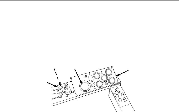
Unscrew plastic retaining nut (Figure 5, Item 3) and push speedometer alarm (Figure 5, Item 2) through dash
panel (Figure 5, Item 5).
24.
Disconnect wires (Figure 5, Item 1) from speedometer (Figure 5, Item 4).
M0504105
Figure 5. Dash Panel Removal.
03/15/2011Rel(1.8)root(maintwp)wpno(M00072)