
TM 5-3810-305-23
0086
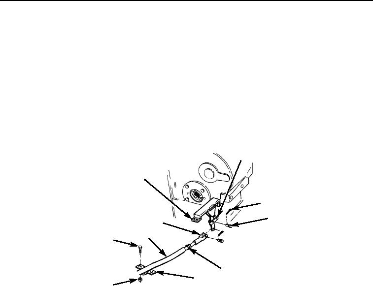
INSTALLATION
Transmission Cable
1.
Install jam nut (Figure 7, Item 5) and clevis (Figure 7, Item 10) on cable (Figure 7, Item 9) and tighten jam nut
(Figure 7, Item 5) against clevis.
2.
Position clamp (Figure 7, Item 6) over cable on bracket (Figure 7, Item 1).
3.
Install two screws (Figure 7, Item 8) and locknuts (Figure 7, Item 7) on bracket (Figure 7, Item 1).
4.
Position clevis (Figure 7, Item 10) on lever (Figure 7, Item 2) and install pin (Figure 7, Item 4) and new cotter
pin (Figure 7, Item 3) through cut out in bracket.
2
1
3
4
10
9
8
5
6
7
M2119105
Figure 7.
Transmission Cable Installation.
03/15/2011Rel(1.8)root(maintwp)wpno(M00093)