
TM 5-3810-305-23
0086
INSTALLATION - Continued
5.
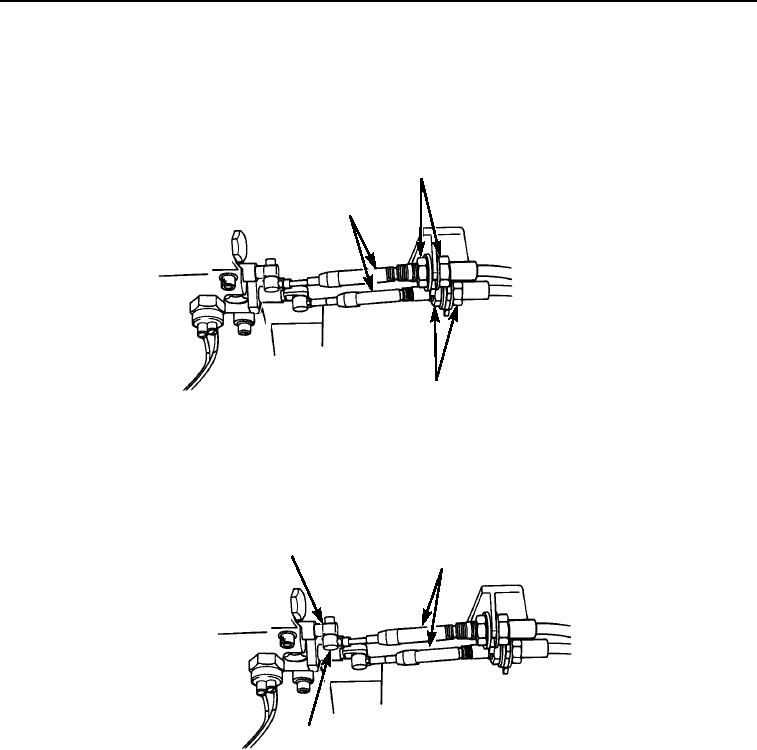
Install nut (Figure 8, Item 3), two washers (Figure 8, Item 2) and nut on each cable (Figure 8, Item 1).
6.
Position two cables (Figure 8, Item 1) in bulkhead bracket on side of transmission. Tighten two jam nuts
(Figure 8, Item 3) to secure each cable.
2,3
1
2,3
M2120105
Figure 8.
Transmission Cable Installation.
7.
Install two pivots (Figure 9, Item 3) on cables (Figure 9, Item 2). Install two pivots in valve body on side of
transmission and install two cotter pins (Figure 9, Item 1) in pivots.
1
2
3
M2118105
Figure 9.
Transmission Cable Installation.
03/15/2011Rel(1.8)root(maintwp)wpno(M00093)