
TM 5-3810-305-23
0093
INSTALLATION
Rear Driveshaft
1.
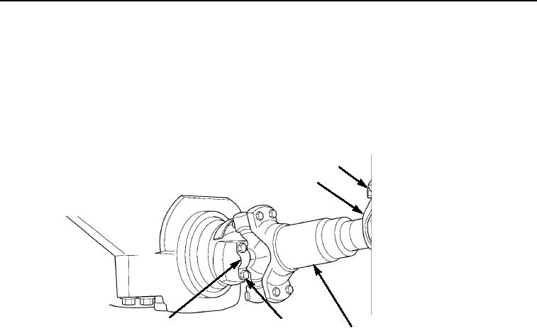
Position driveshaft assembly (Figure 12, Item 3) under vehicle.
2.
Install four capscrews (Figure 12, Item 4) in rear spider bearing assembly (Figure 12, Item 5).
3.
Install four capscrews (Figure 12, Item 1) in front spider bearing assembly (Figure 12, Item 2).
4.
Tighten eight capscrews (Figure 12, Items 1 and 4) to 50 ft-lb (68 Nm).
1
2
5
4
3
M0199105
Figure 12.
Rear Driveshaft Installation.
END OF TASK
FOLLOW-ON MAINTENANCE
1.
Place boom in resting position (TM 5-3810-305-10).
2.
Check for proper operation.
END OF TASK
END OF WORK PACKAGE