
TM 5-3810-305-23
0104
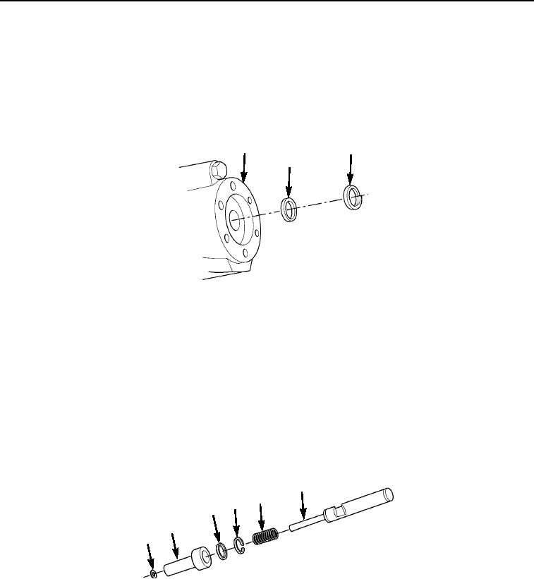
ASSEMBLY - Continued
CAUTION
Two lips of U-cup must point toward inside of brake booster. Use care to avoid nicking or
scratching seal lips.
4.
Install back-up ring (Figure 11, Item 3) and cup (Figure 11, Item 2) and in brake booster valve
housing (Figure 11, Item 1).
1
3
2
M0496105
Figure 11.
Brake Booster Assembly.
5.
Install spring (Figure 12, Item 5) on piston assembly (Figure 12, Item 6).
NOTE
Two lips of U-cup must be away from piston. Use care to avoid nicking or scratching seal lips.
6.
Install back-up ring (Figure 12, Item 4) and cup (Figure 12, Item 3) in piston (Figure 12, Item 2). Do not mar
piston bore.
7.
Install piston (Figure 12, Item 2) over spring (Figure 12, Item 5) and piston assembly (Figure 12, Item 6).
8.
Install retaining ring (Figure 12, Item 1) on piston assembly (Figure 12, Item 6).
6
5
4
3
2
1
M0495105
Figure 12.
Brake Booster Assembly.
03/15/2011Rel(1.8)root(maintwp)wpno(M00115)