
TM 5-3810-305-23
0107
ASSEMBLY
WARNING
When inflating tires, always ensure tires are properly seated. Improperly seated tires can
burst with explosive force.
DO NOT mix one type of wheel with a different type of tire. Improper seating of these
components can cause tire and wheel to fly apart with explosive force.
Failure to follow these warnings may result in serious injury or death to personnel.
1.
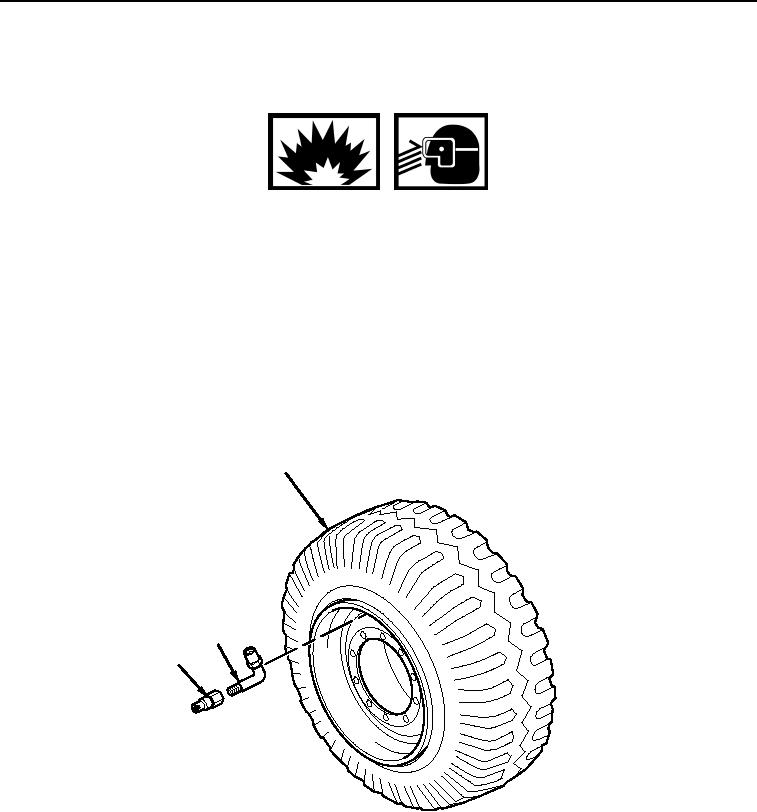
Install new valve stem (Figure 3, Item 2).
2.
Apply lubricant to both beads of tire and wheel rim.
3.
Position wheel flat on floor with valve stem (Figure 3, Item 2) up.
4.
Place tire and wheel assembly (Figure 3, Item 3) into safety cage.
5.
Inflate tire. Recommended tire pressure for the 12.00 x 22.5, 14 PR tire is 115 psi (793 kPa).
3
2
1
M0182105
Figure 3. Tires and Wheels Assembly.
6.
Install valve stem cap (Figure 4, Item 1).
03/15/2011Rel(1.8)root(maintwp)wpno(M00119)