
TM 5-3810-305-23
0153
REMOVAL - Continued
CAUTION
Wipe area clean around all connections to be opened during removal. Cap lines and
hoses and plug openings after removing lines. Contamination of system could result in
premature failure.
NOTE
Tag hoses prior to removal to ensure correct installation.
Use a container to catch any fluid that may drain from hoses or system. Dispose of
fluid IAW local policy and ordinances. Ensure all spills are cleaned up.
Hydraulic reservoir capacity is 23.8 gal. (90.1 L).
1.
Turn dipstick cap 1/4 turn to safety to relieve pressure.
2.
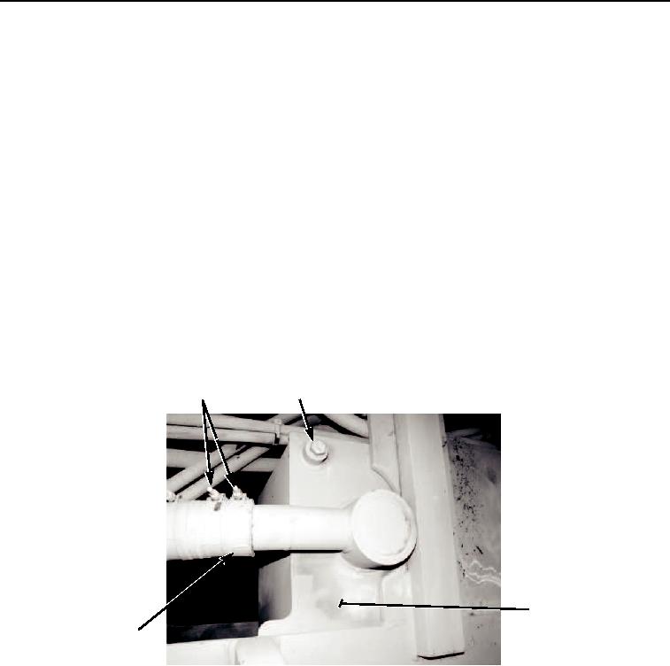
Remove drain plug (Figure 1, Item 2) and o-ring (Figure 1, Item 3). Discard o-ring.
3.
Drain hydraulic reservoir (Figure 1, Item 4) into suitable container.
4.
Remove two clamps (Figure 1, Item 1) and hose (Figure 1, Item 5) from hydraulic reservoir (Figure 1, Item 4)
and drain any hydraulic fluid in hose into suitable container.
1
2,3
4
5
M0336105
Figure 1. Hydraulic Reservoir Removal.
5.
Disconnect hose (Figure 2, Item 11), elbow (Figure 2, Item 10), and o-ring (Figure 2, Item 9). Discard o-ring.
6.
Remove nipple (Figure 2, Item 4), o-rings (Figure 2, Item 5), and dust cap (Figure 2, Item 6). Discard o-rings.
7.
Remove four locknuts (Figure 2, Item 8), washers (Figure 2, Item 7), two capscrews (Figure 2, Item 1), and
washers (Figure 2, Item 2) on reservoir (Figure 2, Item 3).
03/15/2011Rel(1.8)root(maintwp)wpno(M00169)