
TM 5-3810-305-23
0161
DISASSEMBLY - Continued
NOTE
It is not recommended to remove spacer from output shaft. If worn, replace output shaft,
spacer, and o-ring.
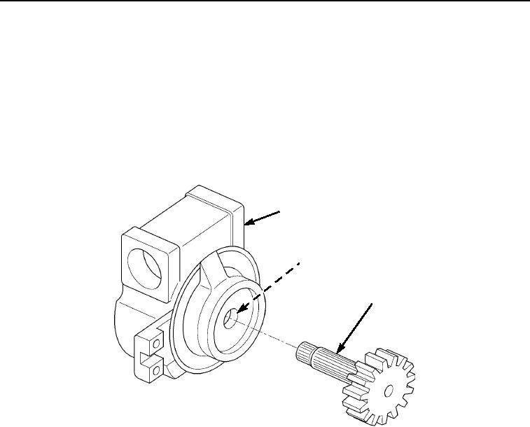
20.
Press output shaft (Figure 8, Item 4) out of housing (Figure 8, Item 1).
21.
Remove seal (Figure 8, Item 2) and one bearing cone (Figure 8, Item 3) from housing (Figure 8, Item 1).
Discard seal.
22.
Remove cone (Figure 8, Item 3) from housing (Figure 8, Item 1).
1
2,3
4
M0605105
Figure 8. Swing Gearbox Output Shaft Disassembly.
03/15/2011Rel(1.8)root(maintwp)wpno(M00180)