TM 5-3810-306-20
b.
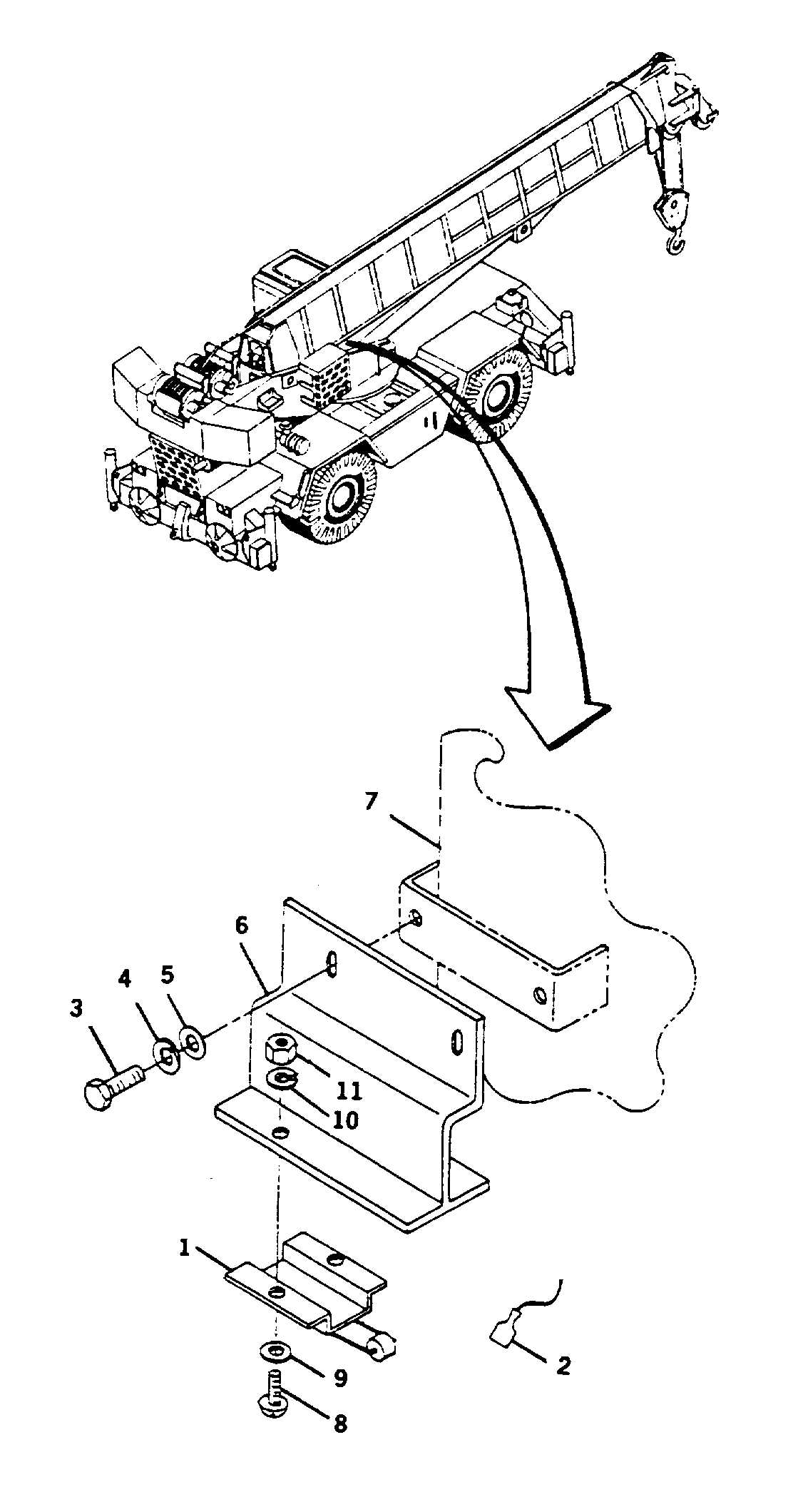
Align switch bracket (6) to air/transmission
swivel (7) and secure with capscrews (3), new
lockwashers (4) and flatwashers (5) hand tight.
c.
Remove tags and connect electrical connectors
(2) to area definition switch (1).
2.
CONNECT GROUND CABLE AT SHUNT. (REFER
TO PAGE 8-109.)
ADJUSTMENT:
1.
ADJUST AREA DEFINITION SWITCH.
a.
Position boom over either side of crane. (Refer
to TM 5-3810306-10.)
b.
Lower boom to 7.5 degrees.
c.
Shutdown crane.
d.
Position ignition switch to ON.
e.
Move area definition switch (1) and bracket
down until switch contacts cam as indicated by
sounding and illumination of warning in cab.
f.
Tighten capscrews.
2.
START
ENGINE
AND
CHECK
SWITCH
OPERATION. (REFER TO TM 5-3810-30610.)
END OF TASK
8-63

