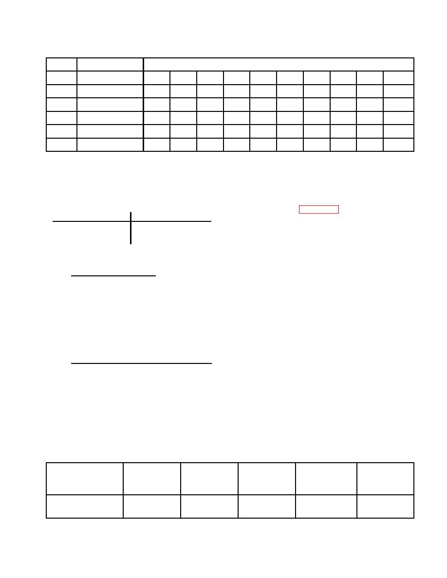
TM 5-3810-307-24-1-1
LED#
OUTPUT NAME
TRANSMISSION SHIFT CONTROL POSITION
F1
F2
F3
F4
F5
F6
N
R3
R2
R1
12
Forward
X
X
X
X
X
X
13
Reverse
X
X
X
14
1st Range
X
X
X
15
2nd Range
X
X
X
X
X
X
19
Splitter
X
X
X
(2)
With transmission shift control
NOTE
lever in N (neutral), check
The APC 100 program defines gears by
conditions of four wheel drive
their ratios, therefore the reverse gears
control system components and
will appear as follows:
checkout kit LEDs as shown in
Shift Lever Position
Checkout Kit Display (G:)
(a) If the input LED functions
R3
R5
improperly, check the DRIVE
R2
R3
AXLE selector switch, cab
R1
R1
harnesses, and APC 100 fuse
and relay box for faulty
connections/components.
5.
Lockup Request Input (25).
(b)
If input LED functions
a.
Position ignition switch to 1 (run); do not
properly, but output LED is not
start engine.
green or yellow at appropriate
times, see output LED color
b.
LED #25 should be illuminated. If not
definitions in CHECKOUT KIT -
illuminated, check APC 100 fuse and
Definition, and repair accordingly.
box
for
faulty
connections/components.
(c) If the input and output LEDs
function
properly,
but
the
6.
Four Wheel Drive Input (04) and Output (35).
pressure at the 4WD disconnect
is not correct, check hoses for
a.
Static Check.
proper routing.
(1)
Start engine.
(d)
If everything functions
properly, but 4WD does not
engage,
transmission
is
defective.
DRIVE AXLE
INPUT LED
OUTPUT LED
PRESSURE AT
4WD
SELECTOR
STATE
STATE
ENERGIZED
4WD
ENGAGED
SWITCH POSITION
DISCONNECT*
2WD
OFF
GREEN
YES
YES
NO
4WD
YELLOW
YELLOW
NO
NO
YES
* With engine running
2-3-23


