SM03-026-0
Page 19
9.
Remove the shaft seal ring.
10. Remove the roller bearings and the seal rings from
the wheel hub.
11. If necessary, remove the wheel studs.
12. Remove the spacer ring from the shoulder of the axle
spindle.
13. Remove the brake assembly from the axle. On wheel
hubs equipped with disc brakes, remove the brake
supports.
Assembly.
NOTE
Take care to ensure the brake control is in
the proper position.
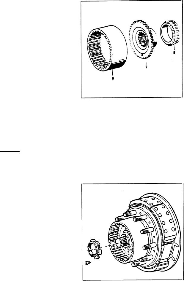
8. Place the ring gear (6) on the carrier (7) and,
1. Install the brake assembly (5) onto the axle. Tighten
according to the type of construction, block it either with
the mounting bolts to the proper torque. Refer to the
screws and LOCTITE 270 or with a lock ring.
proper torque chart. Use LOCTITE as outlined under
LOCTITE USE in this section. On wheel hubs equipped
NOTE
with disc brakes, install brake supports.
The oil compensating hole drilled in the ring
gear carrier (7) must be on the bottom.
CAUTION
The axle spindle mut be free of corrosion
9. Install the ring gear carrier and the ring gear in the
before installing the spacer ring.
wheel hub. Install the assembly onto the axle spindle.
The oil compensating hole drilled in the ring gear carrier
(7) must be on the bottom.
2.
Heat the spacer ring to about 212 deg. F (100 C) and
gently tap the ring onto the shoulder of the axle spindle.
3.
Install the wheel studs.
4. Install the roller bearings and the seal rings into the
wheel hub. Fill the inner bearing with grease.
5.
Install the shaft seal ring with the anti-dust lip facing
out. Fill the seal between the lip seal and the anti-dust lip
with grease.
6.
Install the wheel hub onto the axle spindle.
7. Install the roller bearing and its inner ring (8) up
against the ring gear carrier.

