TM 5-3810-206-35
housing through inlet strainer by the transfer pump. Fuel
between the plungers is forced from the pump through
is forced through the axial passage to pumping cylinder
an outlet port to an injection line, then to the fuel injector.
by transfer pump pressure. As the distributor revolves, a
b. For Engine Model D333TA. This fuel pump is
plunger is forced outward a distance in proportion to
composed of a housing with six cam operated individual
amount of fuel admitted to the pumping cylinder. Further
fuel pumps installed. The pumps may be individually
rotation of the distributor brings its discharge port into
removed while the pump housing is installed on the
registry with an outlet port, and the rollers
accessory drive housing. The transfer pump forces fuel
simultaneously contact the opposing cam lobes, thereby
through a filter, into the pump housing inlet passage,
forcing the plungers toward each other. Fuel trapped
thence to each pump as required.
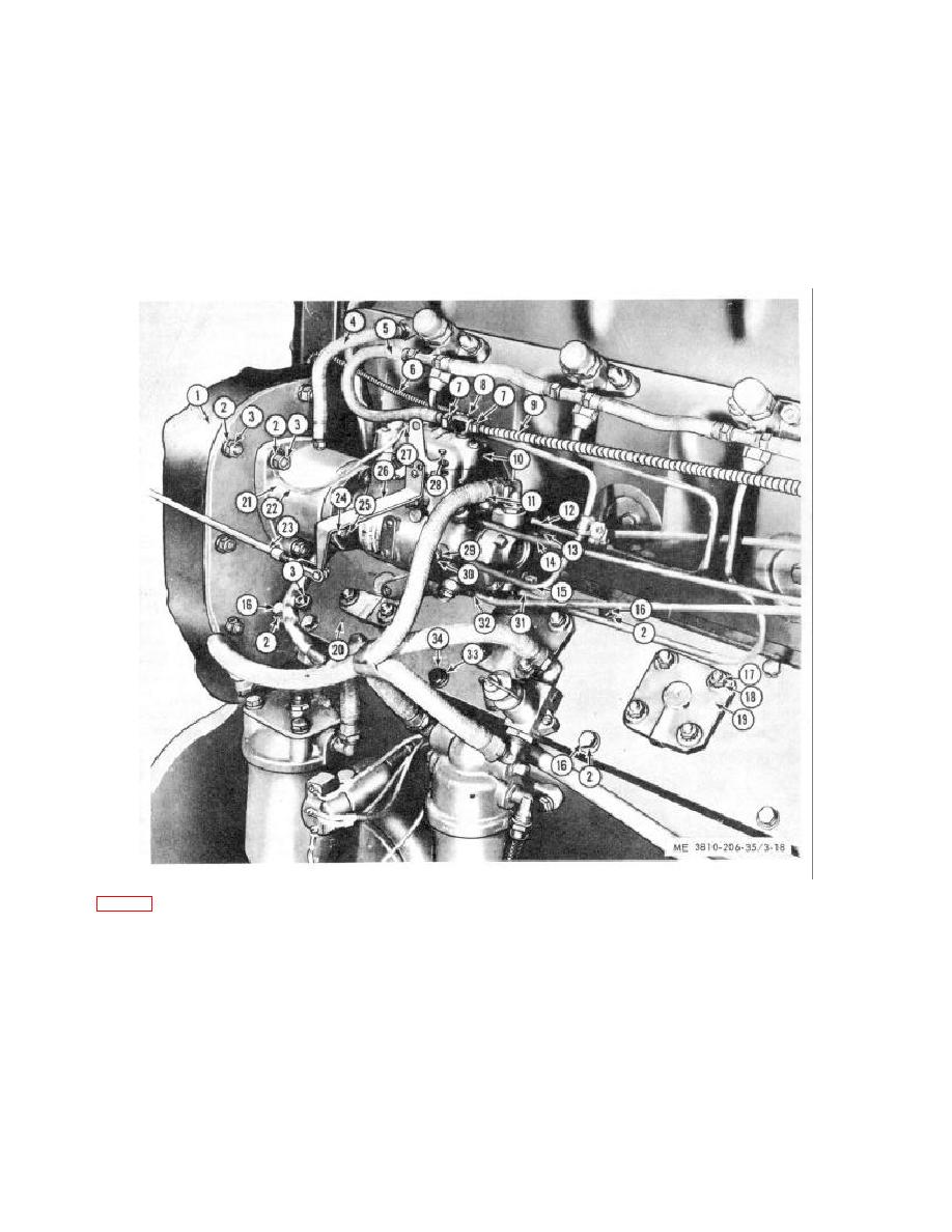
KEY to fig. 3-18:
1
Flywheel housing
8
Shutoff shaft
17
Nut (24 rqr)
25
Nut (3 rqr)
2
Lockwasher
9
Fuel return line
18
Lockwasher
26
Throttle shaft arm
(45 rqr)
10
Fuel injection
(24 rqr)
27
Nut
3
Nut (21 rqr)
pump
19
Exhaust lever
28
Locking screw
4
Oil line
11
Fuel line
support (6 rqr)
29
Lockwasher
5
Fuel return line
12
Fuel line #5
20
Cam cover
30
Headlocking screw
6
Shutoff control
13
Fuel line #3
21
Drive mechanism
31
Fuel line #4
linkage
14
Fuel line #1
22
Ground wire
32
Fuel line #2
7
Connector nut
15
Fuel line #6
23
Throttle rod
33
Capscrew (16 rqr)
(4 rqr)
16
Capscrew (14 rqr)
24
Flatwasher (3 rqr)
34
Flatwasher (24 rqr)
Figure 3-18. Fuel injection pump and drive mechanism removal and installation
3-26


