TM 5-3810-206-35
finger sleeve and recenter seal.
(10) Place insert (22, sheet 2 of fig. 3-17) over
shaft (16) and carefully lower to assembly position.
(11) Install retaining ring in groove with fiat side
of ring resting against insert.
(12) Install shim(s) (13) over shaft and spacer
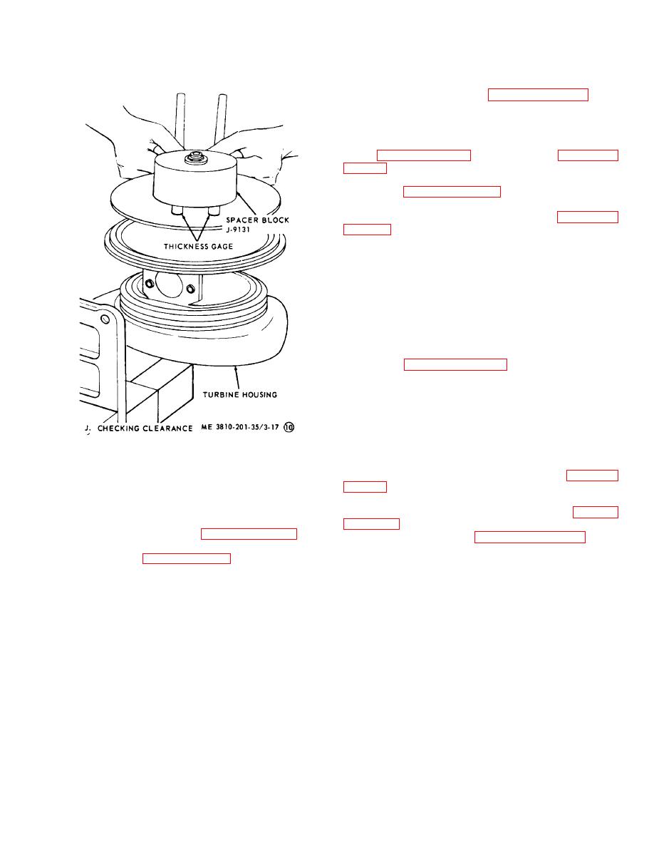
block (sheet 7 of fig. 2-1) resting on shim (sheet 10 of
(13) Apply film of grease to threads and face of
locknut (14, sheet 2 of fig. 3-17). Install and torque nut
30 ft-lb. Check clearance between block and face of
housing with two sets of thickness gages (sheet 10 of
0.003, 0.005 and 0.010 inch thickness are available to
obtain correct clearance.
Note. Torque locknut 30 ft-lb each
time clearance is checked.
(14) With block in place check end play. End
play shall be 0.004-0.006 inch. Correct end play will be
obtained by adding or removing shims.
(15) Apply film of grease to bore of compressor
wheel, (15, sheet 2 of fig. 3-17). Remove all grease
from back face of wheel.
(16) Place compressor wheel over shaft. Place
unit in arbor press with square extension on turbine
wheel resting on block and place tool on wheel. Make
certain wheel is starting squarely on shaft, press against
tool until wheel bottoms. Remove tool and replace unit
in vise.
Figure 3-17. Turbocharger details (sheet 10 of 10).
(17) Apply film of grease to threads and back
face of locknut, install and torque nut 30 ft-lb (sheet 3 of
(6) Install performed packing in groove in
bearing housing.
(18) Recheck for 0.019 to 0.022 inch clearance
(7) Lubricate preformed pac king with light film of
between compressor and housing as shown in (sheet 10
grease.
(8) Install piston ring (17, sheet 2 of fig. 3-17) in
(19) Place clamp (sheet 1 of fig. 3-17) over
groove in flinger sleeve (11) and turbine shaft (16), using
bearing housing.
ring expander sleeve (sheet 6 of fig. 2-1). Position seals
(20) Install packing and compressor cover on
with gaps 180 apart.
bearing housing. Earlier models have no groove for
(9) Using flinger pressure only, carefully install
preformed packing. Align assembly marks and position
flinger sleeve, with piston ring entering bore in insert.
clamps on flanges.
(21) Grease clamp threads and face of nut.
Caution: Do not force. If piston seal
Install and torque nut to 10 ft-lbs.
does not enter bore easily, remove
Section VII. FUEL INJECTION PUMPS
It is the single cylinder, opposed plunger, inlet metering,
3-16. General
distributor type. This pump contains, as integral parts of
a. For Engine Model 687C-18-ES.
This fuel
the unit, a positive displacement vane type transfer
injection pump meters fuel to each cylinder at precisely
pump, and flyweight governor. Fuel is drawn into pump
timed intervals under pressure of 2.200 psi.
3-25


