TM 5-3810-206-35
chambers. Inspect compression release mechanism for
Note. Be sure water directors, seals,
bent shaft, weak spring, or plunger. Repair or replace
and ferrule are properly installed.
damaged shaft Replace defective spring or plunger.
Align notch on director with V-mark
e. Reassembly and Installation.
on head.
Also assure that pre-
(1) Install bearing caps and sleeves by
combustion chamber is correctly
reversing the procedures in c above.
positioned (fig. 3-61 and 3-62).
(2) Reassemble and install cylinder head by
reversing procedures in b above. Tighten cylinder head
(3) Complete
installation
by
reversing
holddown bolts (in the numerical sequence shown in fig.
procedures in steps (1) through (6) of a above.
Section XVI. PISTON AND CONNECTING ROD
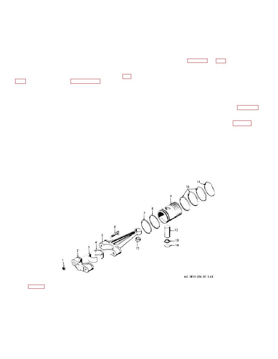
(1) Remove cylinder head and liner (para 3-54).
3-56.
General
(2) Remove piston and connecting rod from
The piston and connecting rods of both engines are
cylinder head and liner.
similar in construction, with the major differences being
(3) Remove upper bearing half (4, fig. 3-63).
in the number of rings used, length of piston skirt, rod
(4) Remove two plugs (14), retaining ring (13),
configuration, and ring placement.
and piston pin (12), then separate rod (5) from piston (9).
(5) Remove piston rings (7, 8, 10, and 11) from
piston (9).
3-57.
Piston and Connecting Rod (Engine 687C-18-
(6) Remove sleeve bearing (15) from rod (5).
ES)
(7) Repeat steps (2) through (6) above for each
a. Removal and Disassembly.
cylinder.
KEY to fig. 3-63:
1
Nut (12 rqr)
5
Rod (6 rqr)
9
Piston (6 rqr)
13
Retaining ring (6 rqr)
2
Rod cap (6 rqr)
6
Bolt (12 rqr)
10
Piston ring (18 rqr)
14
Plug (12 rqr)
3
Lower bearing half
7
Piston ring (6 rqr)
11
Piston ring (6 rqr)
15
Sleeve bearing (6 rqr)
(6 rqr)
8
Piston ring (6 rqr)
12
Piston pin (6 rqr)
4
Upper bearing half
(6 rqr)
Figure 3-63. Piston and connecting rod, (Engine Model 687C-18-ES), exploded view,
3-75


