TM 5-3810-206-35
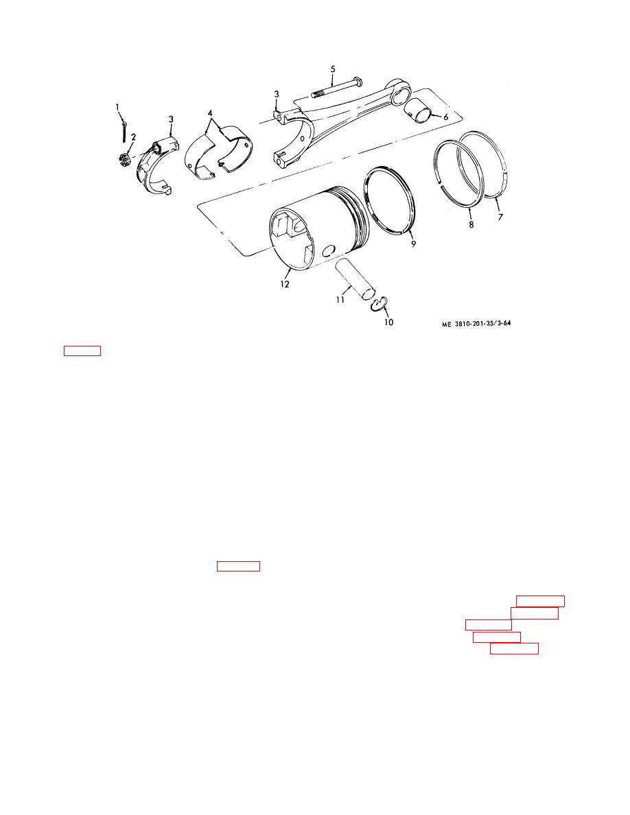
KEY to fig. 3-64:
1
Cotterpin (12 rqr)
4
Bearing halves
7
Piston ring (6 rqr)
10 Retaining ring (2 rqr)
2
Nut (12 rqr)
5
Bolt (12 rqr)
8
Piston ring (6 rqr)
11 Piston pin (6 rqr)
3
Connecting rod
6
Sleeve bearing (6 rqr)
9
Piston ring (6 rqr)
12 Piston
Figure 3-64. Piston and connecting rod, for engine model D333TA, exploded view.
Section XVII. CRANKSHAFT AND MAIN BEARINGS
main bearings. They are steel backed aluminum lined
3-59. General
precision type. Tabs are punched outward on bearing
a. Engine Model 687C-18-ES.
The crankshaft
half at parting line, and fit into recesses in block and
gear is installed on rear end of crankshaft and located
bearing cap to prevent it rotating. The crankshaft thrust
(positioned) by two large drive dowel pins, which
is taken on flange of lower half of rear main bearing.
extends through the gear, and locates flywheel as well.
The upper half of rear main bearing does not have a
One of these dowel pins is offset slightly to prevent
flange.
incorrect assembly. Crankshaft thrust is taken on rear
main journal. End clearance of the crankshaft must not
3-60. Crankshaft and Main Bearings (Engine Model
exceed 0.020 inch. Bearing caps (7, fig. 3-49) should
687C-18-ES)
not be filed or shimmed. The bearing halves are held in
place by tangs at split line. Both halves of the main
a. Removal and Installation.
bearings allow continuous lubrication. Main bearing
(1) Remove engine front cover (para 3-48).
caps are numbered from front to rear, and must be
(2) Remove flywheel housing (para 3-40).
returned to same place from which removed, with
(3) Remove oil pan (para 3-43).
numbered side toward camshaft.
(4) Remove oil pump (para 3-45).
b. Engine Model D333TA. The crankshaft gear is
(5) Remove capnuts (8, fig. 3-49), caps (11)
installed on front end of crankshaft and is located by key,
from the six rods, then push rods and pistons up in
with a seal between gear and damper. There are seven
cylinder.
3-77


