
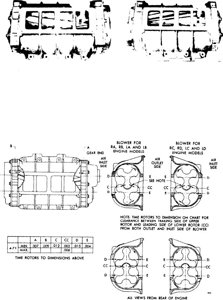
Figure 11D-20. Measuring " C C " and "C" Clearances Between Blower Lobes
edge of the UPPER rotor and LEADING
taken 1" from the governor end, at the
edge of
LOWER rotor ("CC"
the
center, and 1" from the drive end.
clearance) measured from both the inlet
and outlet sides.
If possible, keep this
2. After determining the amount one ro-
clearance to the minimum (0.002"). Then
tor must be revolved to obtain the prop-
check the clearance between the LEAD-
er clearance, a d d s h i m s b a c k o f t h e
ING
edge
of
the UPPER and
the
proper gear as shown in Figure 11D-22
TRAILING edge of the LOWER rotors
on page 11D-16 to produce the desired
r e s u l t . When more or less shims are re-
("C" clearance) for the minimum clear-
ances
shown
in
Figure
11D-21.
quired, both gears must be removed from
Rotor-to-rotor measurements should be
the rotors.
Placing a 0.003" shim in
Figure 11D-21. Chart of Minimum Clearances
Air Intake System