
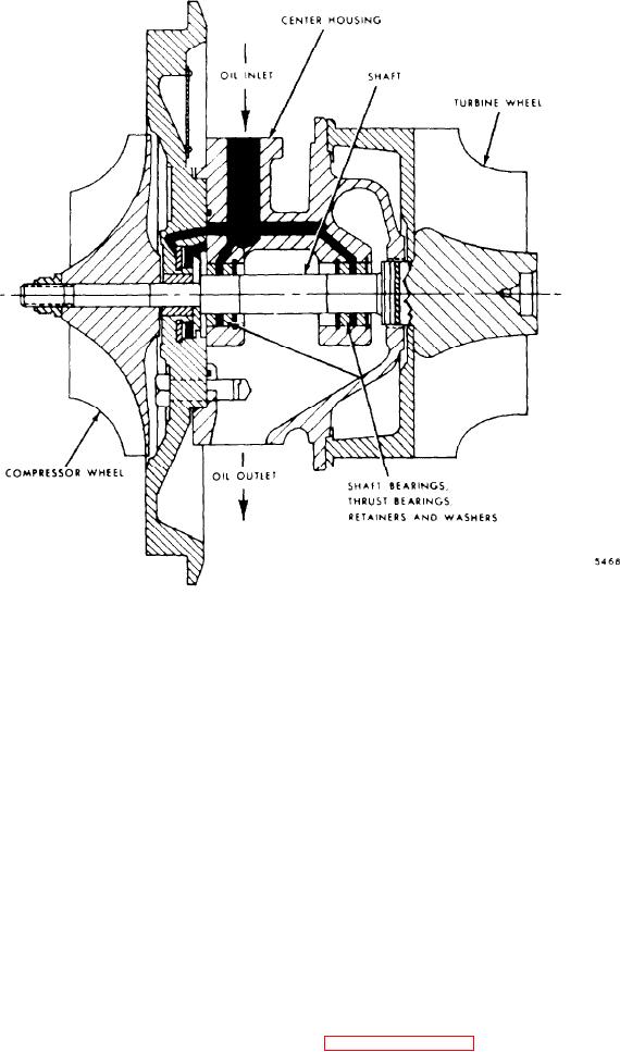
Figure 11D-28. Turbocharger Oil Flow Diagram
NOTE
NOTE
Do not attempt to remove carbon or
Do not operate the engine if leaks
dirt buildup on the compressor or
are found in the turbocharger
turbine wheels without removing
ducting or if the air cleaner is not
filtering efficiently. Dust leaking
the turbocharger from the engine.
The blades on the wheels must be
into the air ducting can damage
thoroughly cleaned.
If chunks of
the turbocharger and the engine.
carbon are left on the blades, an
unbalance condition w o u l d e x i s t
and subsequent failure of the bear-
Remove the inlet duct to the turbocharg-
would
ings
result
if
the
er compressor housing and check for
turbocharger is operated. Howev-
carbon or dirt buildup on the impeller or
it
is
not
necessary to
i n t h e h o u s i n g . E x c e s s i v e accumulations
er,
disassemble the turbocharger to
indicate either a leak in the ducting or a
remove dirt or dust buildup.
R e m o v e all
faulty air filtering system.
such accumulations and determine and
Refer to "Trouble-
correct the cause,
For proper operation, the turbocharger
shooting, Specifications & Service Tools"
rotating assembly must turn free. When-
o n p a g e 1 1 D - 3 1 . U n e v e n deposits left on
ever the exhaust ducting is removed,
the compressor wheel can affect the bal-
spin the turbine wheel by hand.
bearing
premature
If it
cause
ance
and
does not spin freely, refer to Chart 1 of
failure.
Figure 11D-29 on page 11D-21. Inspect
the compressor and turbine wheels for
nicks or loss of material.
Both wheels
are precision balanced. A broken or