
The turbine wheel is located in the tur-
bine housing and is mounted on one end
The compressor
of the turbine shaft.
wheel is located in the compressor hous-
ing and is mounted on the opposite end
of the turbine wheel shaft to form an in-
tegral rotating assembly.
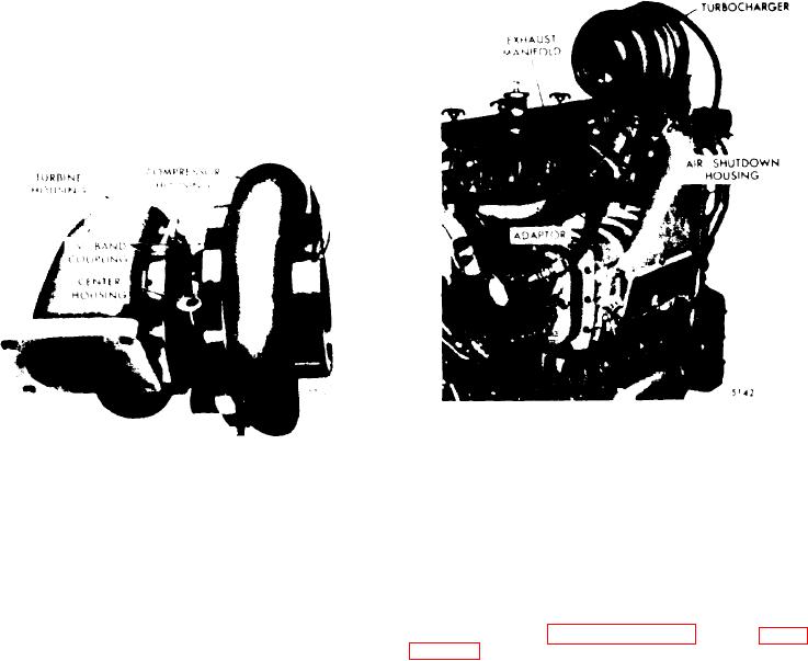
F i g u r e 11D-25. Turbocharger Mounting
Figure 11D-24. Turbocharger Assembly
Operation
The rotating assembly consists of a tur-
The turbocharger is mounted on the ex-
bine wheel and shaft assembly, piston
haust outlet flange of the engine exhaust
compressor
thrust
spacer,
ring(s),
manifold.
After the engine is started,
wheel and wheel retaining nut. The ro-
the exhaust gases flowing from the en-
tating assembly is supported on two
gine and through the turbine housing
pressure lubricated bearings which are
cause the turbine wheel and shaft to ro-
retained in the center housing by snap
on
tate
(see
rings.
Internal oil passages are drilled
The gases are discharged into
in the center housing to provide lubri-
the atmosphere after passing through the
shaft
wheel
turbine
the
cation to
turbine housing.
bearings, t h r u s t w a s h e r , t h r u s t c o l l a r
and thrust spacer.
The compressor wheel, which is mounted
on the opposite end of the turbine wheel
The turbine housing is a heat resistant
shaft,
rotates with the turbine wheel.
alloy casting which encloses the turbine
The compressor wheel draws in fresh
wheel and provides a flanged engine ex-
compresses i t a n d d e l i v e r s h i g h
air,
haust gas inlet and an axially located
pressure air through the engine blower
The
turbocharger exhaust gas outlet.
to the engine cylinders.
turbine housing is secured to the turbine
end of the center housing with a "V"
During operation, the turbocharger re-
band coupling, thus providing a compact
sponds to the engine load demands by
and vibration free assembly.
reacting to the flow of the engine ex-
haust gases.
As the engine power out-
The compressor housing which encloses
increases
decreases,
or
the
the compressor wheel, provides an ambi-
put
turbocharger responds to the engine's
ent air inlet and a compressed air dis-
demand to deliver the required amount of
The compressor housing
charge outlet.
air under all conditions.
is secured to the compressor end of the
center housing backplate assembly with a
"V" band coupling.
Lubrication
Lubricating oil for the turbocharger is
supplied under pressure through an ex-
11D-18