TM 5-3810-305-23
0029
INSTALLATION - Continued
NOTE
Maximum TIR is determined by diameter of housing bore. Replace housing if out
of specification.
7.
Specification of bore diameter is 17.625 to 17.630 inches (447.68 to 447.80 mm). TIR maximum is
0.008 inch (0.20 mm).
CAUTION
DO NOT force crankshaft beyond point where bearing clearance has been removed.
DO NOT use flywheel housing as a fulcrum. Failure to follow this caution may cause damage
to equipment.
8.
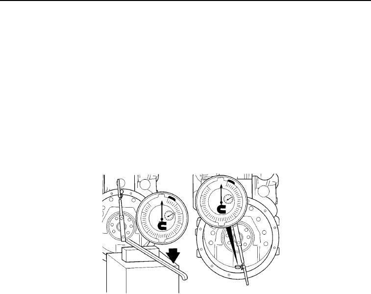
Determine adjustment for main bearing clearance by raising rear of crankshaft to its upper hit. Use a floor-
mounted support with padded pry bar to raise crankshaft and record reading.
M0221105
Figure 6. Flywheel Installation.
9.
Calculate bearing clearance adjustment by subtracting one-half of reading obtained in Step 8 from reading
obtained at 6 o'clock position.
EXAMPLE:
Total bearing clearance = +0.003 inch (+0.08 mm)
One-half bearing clearance = +0.0016 inch (+0.040 mm)
6 o'clock position reading = +0.008 inch (+0.20 mm)
Adjusted 6 o'clock reading = +0.0064 inch (+0.162 mm)
03/15/2011Rel(1.8)root(maintwp)wpno(M00034)

