
TM 5-3810-305-23
FIELD MAINTENANCE
TIMING PIN ASSEMBLY MAINTENANCE
INITIAL SETUP:
References
Tools and Special Tools
Tool Kit, General Mechanic's (WP 0171, Table 1,
Item 17)
Equipment Condition
Boom in horizontal position and fully retracted (TM
Materials/Parts
5-3810-305-10)
Cleaning Compound, Solvent, Type III (WP 0170,
Battery cables disconnected (WP 0076)
Table 1, Item 9) Qty: 1
Cylinder head removed (WP 0027)
O-Ring (WP 0172, Table 1, Item 77) Qty: 1
Front gear cover removed (WP 0032)
Personnel Required
(Two)
REMOVAL
1.
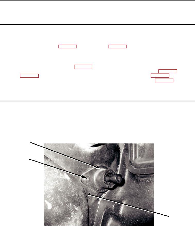
Remove two screws (Figure 1, Item 3) from timing pin housing (Figure 1, Item 1).
2.
Remove timing pin housing (Figure 1, Item 1) from gear housing (Figure 1, Item 2).
1
3
2
M0019105
Figure 1.
Timing Pin Assembly Removal.
03/15/2011Rel(1.8)root(maintwp)wpno(M00038)