
TM 5-3810-305-23
0067
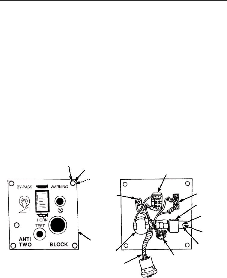
ASSEMBLY
1.
Install WARNING light (Figure 2, Item 14), washer, and nut to control panel (Figure 2, Item 13).
2.
Install HORN switch (Figure 2, Item 4) by pushing HORN switch in hole until spring clips lock.
3.
Connect two wires to HORN switch (Figure 2, Item 4).
4.
Install TEST switch (Figure 2, Item 10), washer, and nut to control panel (Figure 2, Item 13).
5.
Connect two wires to TEST switch (Figure 2, Item 10).
6.
Install HORN (Figure 2, Item 12) and plastic nut on control panel (Figure 2, Item 13).
7.
Connect two wires to HORN (Figure 2, Item 12).
8.
Connect five wires to relay (Figure 2, Item 6).
9.
Install BY-PASS toggle switch (Figure 2, Item 5), washers, and nut to control panel (Figure 2, Item 13).
10.
Connect two wires to BY-PASS toggle switch (Figure 2, Item 5) with two bolts.
END OF TASK
INSTALLATION
1.
Connect plug (Figure 2, Item 11) on rear of control panel (Figure 2, Item 13) to connector in cab.
2.
Install four tubes (Figure 2, Item 3), washers (Figure 2, Item 2), and bolts (Figure 2, Item 1) to control panel
(Figure 2, Item 13).
3.
Install control panel (Figure 2, Item 13) to vehicle.
1
2
4
3
5
14
6
7
8
13
9
12
10
M0089105
11
Figure 2. Control Panel Maintenance.
END OF TASK
03/15/2011Rel(1.8)root(maintwp)wpno(M00073)