
TM 5-3810-305-23
0084
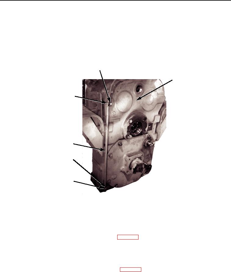
REMOVAL
1.
Remove cap screw (Figure 1, Item 1) and clamp (Figure 1, Item 6) from top rear of transmission
(Figure 1, Item 2).
2.
From the bottom of vehicle, remove tubing nut (Figure 1, Item 4) and remove dipstick tube (Figure 1, Item 5)
from elbow (Figure 1, Item 3).
3.
Remove elbow (Figure 1, Item 3) from transmission (Figure 1, Item 2).
1
2
6
5
4
3
M2105105
Figure 1. Transmission Dipstick Tube Removal.
END OF TASK
CLEANING
Clean parts IAW General Maintenance Instructions (WP 0162).
END OF TASK
INSPECTION
Inspect parts IAW General Maintenance Instructions (WP 0162).
END OF TASK
03/15/2011Rel(1.8)root(maintwp)wpno(M00090)