TM 5-3810-305-23
0087
ADJUSTMENT
1.
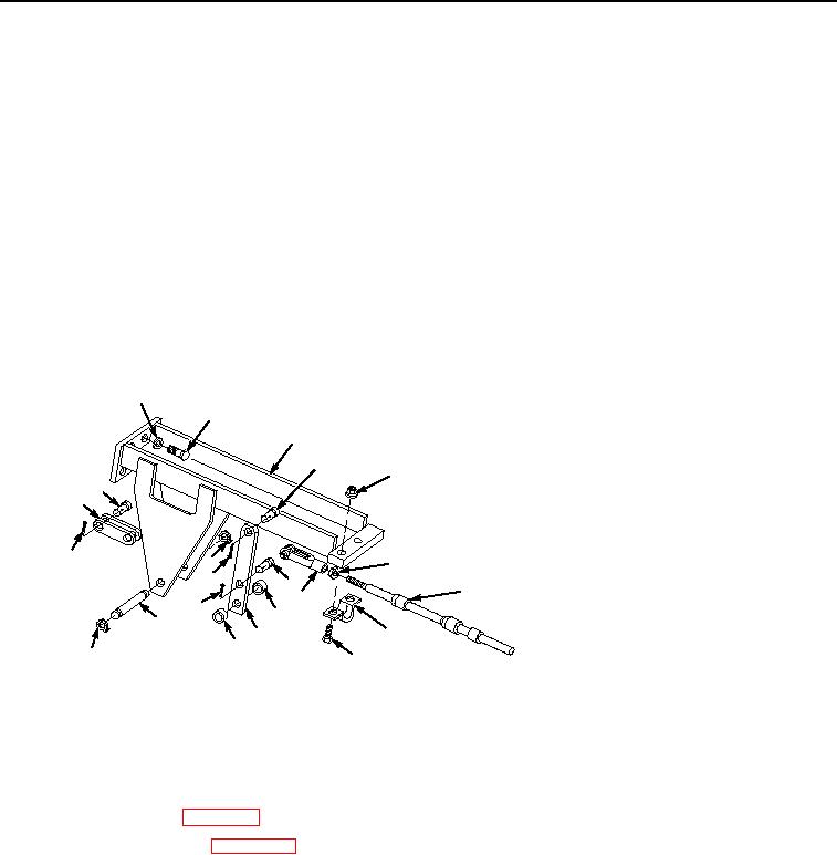
Remove cotter pin (Figure 3, Item 14) and pin (Figure 3, Item 11).
2.
Put lever in cab into two-wheel drive position.
3.
Pull shaft spool on transmission to full out position.
4.
Thread jam nut (Figure 3, Item 6) all the way onto rod end (Figure 3, Item 7).
5.
Thread clevis (Figure 3, Item 10) either up or down rod end (Figure 3, Item 7) to adjust.
6.
Position clevis (Figure 3, Item 10) on lever (Figure 3, Item 13).
7.
Install pin (Figure 3, Item 11) and new cotter pin (Figure 3, Item 14) through lever (Figure 3, Item 13) and
clevis (Figure 3, Item 10).
8.
Check lever in cab for full movement from stop to stop. Repeat Steps 1 through 7 if not adjusted correctly.
9.
Tighten jam nut (Figure 3, Item 6) to clevis (Figure 3, Item 10).
1
2
3
4
5
20
19
18
6
16
15
11
7
10
14
12
17
8
13
12
M2140105
16
9
Figure 3. Transmission Controls Maintenance.
END OF TASK
FOLLOW-ON MAINTENANCE
1.
Install deck plates (WP 0122).
2.
Connect battery cables (WP 0076).
3.
Place boom in resting position (TM 5-3810-305-10).
4.
Outriggers raised and unextended (TM 5-3810-305-10).
END OF TASK
END OF WORK PACKAGE
03/15/2011Rel(1.8)root(maintwp)wpno(M00094)

