
TM 5-3810-305-23
0095
INSTALLATION
WARNING
Wear protective equipment while heating and handling spacer. Failure to follow this warning
may result in serious injury to personnel.
1.
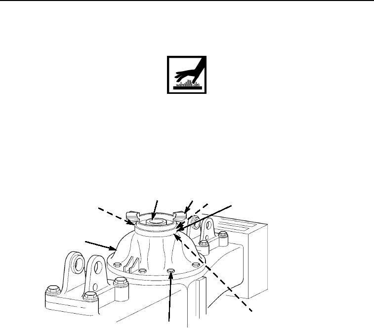
Lubricate and install new input yoke seal (Figure 3, Item 5) flush.
2.
Heat spacer (Figure 3, Item 3) to approximately 350F (176C). Install spacer (Figure 3, Item 3) and trunnion
(Figure 3, Item 4).
3.
Install input yoke (Figure 3, Item 2), dust shield (Figure 3, Item 8) and new pinion nut (Figure 3, Item 1). Tighten
pinion nut (Figure 3, Item 1) to 405 to 433 ft-lb (549 to 587 Nm). Stake pinion nut (Figure 3, Item 1) in two
locations 180 degrees apart.
1
2
3
8
4
7
5
6
M0315105
Figure 3. Front Differential Installation.
03/15/2011Rel(1.8)root(maintwp)wpno(M00105)