
TM 5-3810-305-23
0103
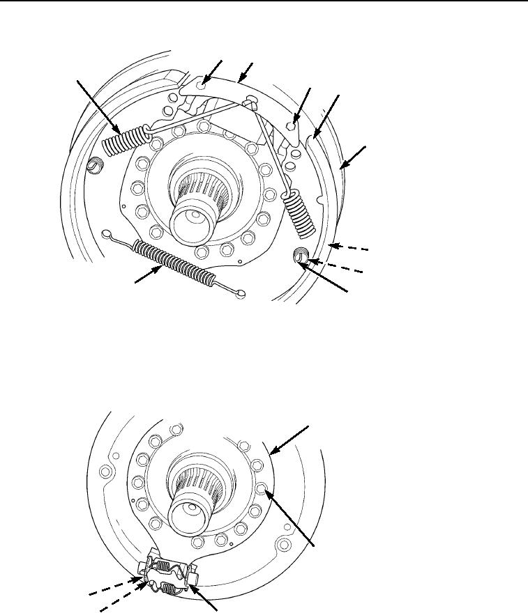
INSTALLATION - Continued
2
3
1
4
5
6
7
8
10
9
M0191105
Figure 7. Brake Assembly Installation.
8.
Loosen bolt (Figure 8, Item 5) to allow automatic adjuster (Figure 8, Item 3) to move back and forth.
9.
Using a feeler gage through the inspection holes, center the brake assembly so there is an equal amount of
clearance at each side.
10.
With brake centered, tighten bolt (Figure 8, Item 5) to 60 ft-lb (82 Nm).
1
2
5
M0192105
3
4
Figure 8. Brake Assembly Installation.
03/15/2011Rel(1.8)root(maintwp)wpno(M00114)