
TM 5-3810-305-23
0103
REMOVAL - Continued
1
2
5
M0192105
3
4
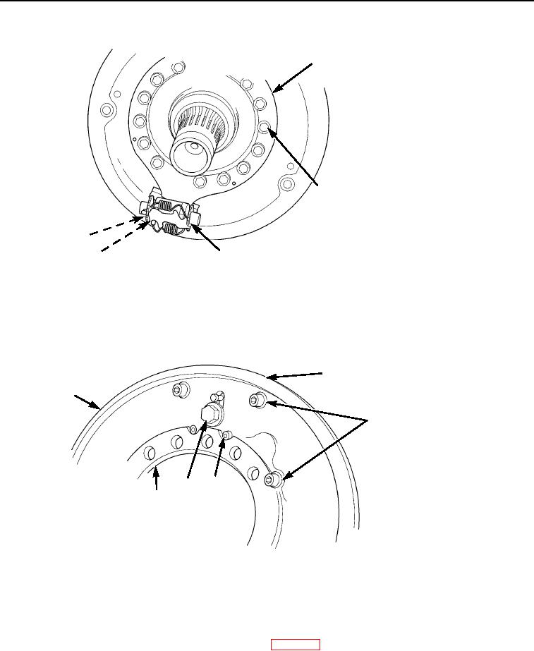
Figure 2.
Brake Assembly Removal.
7.
Remove banjo fitting assembly (Figure 3, Item 5), six bolts and washers (Figure 3, Item 3), and dust shield
(Figure 3, Item 1) from brake spider assembly (Figure 3, Item 6).
8.
Remove two bolts (Figure 3, Item 4) and wheel cylinder (Figure 3, Item 2) from brake spider
assembly (Figure 3, Item 6).
2
1
3
4
5
6
M0193105
Figure 3.
Brake Assembly Removal.
END OF TASK
CLEANING
Clean parts IAW General Maintenance Instructions (WP 0162).
END OF TASK
03/15/2011Rel(1.8)root(maintwp)wpno(M00114)