
TM 5-3810-305-23
0123
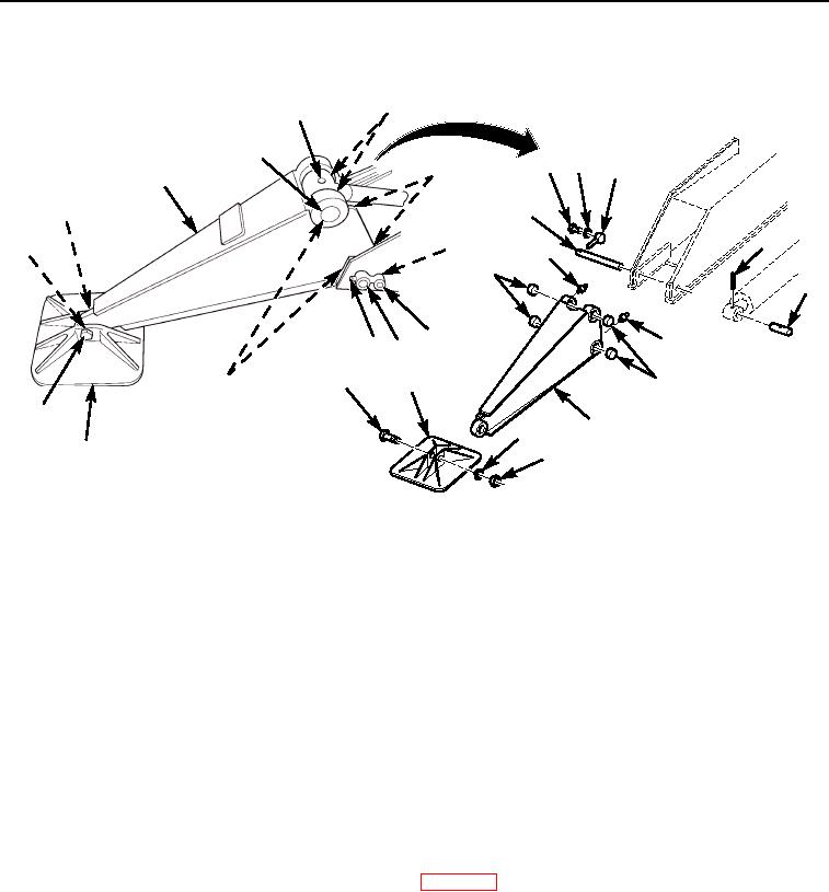
REMOVAL - Continued
4
3
2
6
7
9
5
1
14
8
3
13
6
5
10
2
7
5
98
12
10
10
11
12
1
13
11
14
M0585105
Figure 1. Outrigger Assembly Removal.
END OF TASK
DISASSEMBLY
1.
Remove nut (Figure 1, Item 14), washer (Figure 1, Item 13), bolt (Figure 1, Item 12), and pad
(Figure 1, Item 11) from beam (Figure 1, Item 1).
2.
Remove two grease fittings (Figure 1, Item 4) and two grease fittings (Figure 1, Item 5) from
beam (Figure 1, Item 1).
3.
Using a press, remove four bushings (Figure 1, Item 10) from beam (Figure 1, Item 1).
END OF TASK
CLEANING
Clean parts IAW General Maintenance Instructions (WP 0162).
END OF TASK
03/15/2011Rel(1.8)root(maintwp)wpno(M00138)