
TM 5-3810-305-23
0129
REMOVAL - Continued
Control Valve Cable - Continued
2.
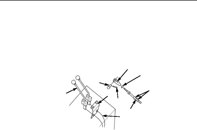
Remove cotter pin (Figure 2, Item 7), pin (Figure 2, Item 2), and yoke (Figure 2, Item 3) from lever assembly
(Figure 2, Item 1). Discard cotter pin.
3.
Remove jam nut (Figure 2, Item 4) and remove yoke (Figure 2, Item 3) from vehicle.
4.
Loosen locking nuts (Figure 2, Item 5) and pull cable (Figure 2, Item 9) from bracket (Figure 2, Item 8).
5.
Remove two locking nuts (Figure 2, Item 5) and washers (Figure 2, Item 6) from cable (Figure 2, Item 9).
3
4
2
5
1
8
7
6
9
M0559105
Figure 2. Valve Control Cable Removal.
03/15/2011Rel(1.8)root(maintwp)wpno(M00145)