
TM 5-3810-305-23
0129
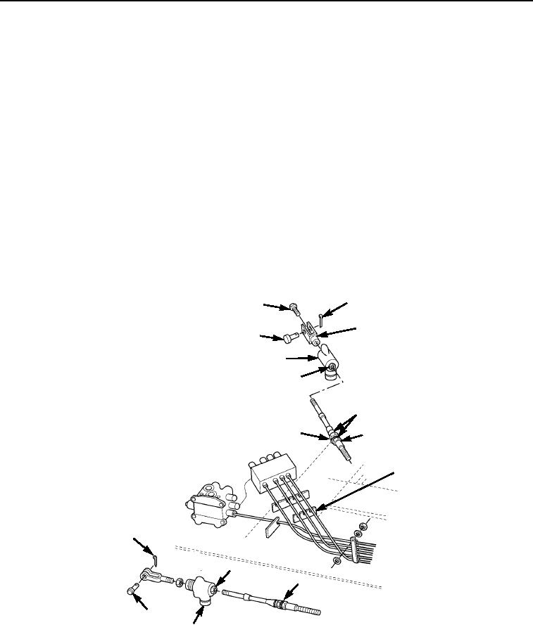
INSTALLATION
Boom Hoist, Extend, And Winch Cable
NOTE
Before tightening jam nut, see adjustment procedure.
1.
Install clevis (Figure 6, Item 3) and capscrew (Figure 6, Item 1) on end of disconnect assembly
(Figure 6, Item 8), telescope and boom hoist cable only.
2.
Install jam nut (Figure 6, Item 10) and disconnect assembly (Figure 6, Item 8) on cable end. Tighten jam nut
securing disconnect assembly (Figure 6, Item 8) on cable end.
3.
Connect two wires on disconnect assembly (Figure 6, Item 8). Note tag from removal.
4.
Position cable (Figure 6, Item 5) in place and install pin (Figure 6, Item 9) and new cotter pin
(Figure 6, Item 2) on clevis (Figure 6, Item 3).
5.
Install washers (Figure 6, Item 7) and new locking nuts (Figure 6, Item 4) on cable (Figure 6, Item 5).
6.
Tighten two new locking nuts (Figure 6, Item 4) securing cable (Figure 6, Item 5) in bracket (Figure 6, Item 6).
7.
Check cable (Figure 6, Item 5) operation for correct adjustment and movement.
2
1
3
9
8
10
4
7
5
6
2
10
7
9
8
M0562105
Figure 6. Boom Hoist, Extend, and Winch Cable Installation.
03/15/2011Rel(1.8)root(maintwp)wpno(M00145)