
TM 5-3810-305-23
0136
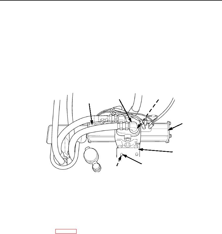
INSTALLATION
1.
Position outrigger solenoid valve (Figure 10, Item 4) over mounting holes in outrigger box and install four
capscrews (Figure 10, Item 6), washers (Figure 10, Item 8), and nuts (Figure 10, Item 7) on mounting
bracket (Figure 10, Item 5).
2.
Install three elbows (Figure 10, Item 2) and new o-rings (Figure 10, Item 3) on outrigger solenoid valve
(Figure 10, Item 4).
3.
Connect three hoses (Figure 10, Item 1) on elbows (Figure 10, Item 2).
4.
Connect four electric wires to outrigger solenoid valve (Figure 10, Item 4).
5.
Close dipstick cap.
2
3
1
4
5
6
7,8
M0087105
Figure 10.
Outrigger Solenoid Valve Installation.
END OF TASK
FOLLOW-ON MAINTENANCE
1.
Check hydraulic oil level. Fill to proper level, if necessary (TM 5-3810-305-10).
2.
Connect battery cable (WP 0076).
3.
Place boom in resting position (TM 5-3810-305-10).
4.
Check for proper operation.
END OF TASK
END OF WORK PACKAGE