
TM 5-3810-305-23
0137
ADJUSTMENT
1.
Start engine and rotate upperstructure approximately 45 degrees. Shut engine OFF (TM 5-3810-305-10).
2.
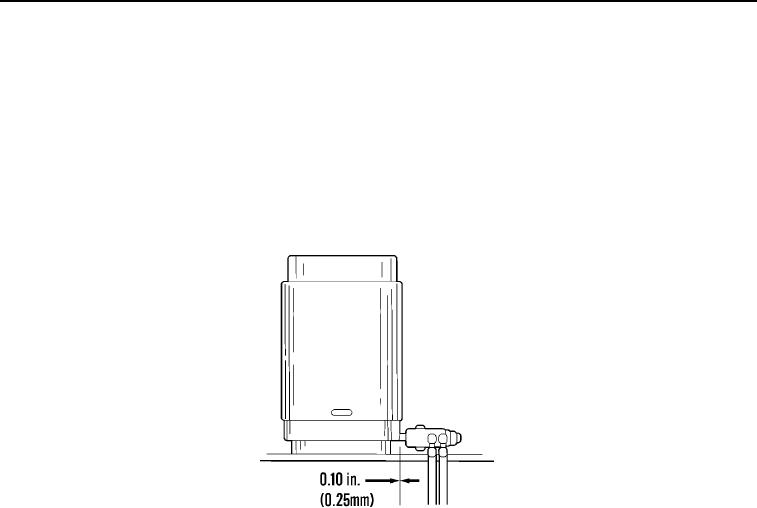
Insert 0.010 inch (0.25 mm) gage between axle lockout valve rollers and high area of cam surface on rotary
manifold. Slide axle lockout valve toward rotary manifold until axle lockout valve spring is fully compressed
and hold in that position while tightening capscrews (Figure 2, Item 1).
3.
Remove 0.010 inch (0.25 mm) gage.
M0323105
Figure 3. Axle Lockout Valve Adjustment.
END OF TASK
FOLLOW-ON MAINTENANCE
1.
Check hydraulic oil level. Fill to proper level, if necessary (TM 5-3810-305-10).
2.
Place boom in resting position (TM 5-3810-305-10).
3.
Check for proper operation.
END OF TASK
END OF WORK PACKAGE
03/15/2011Rel(1.8)root(maintwp)wpno(M00153)