TM 5-3810-305-23
0142
INSTALLATION
1.
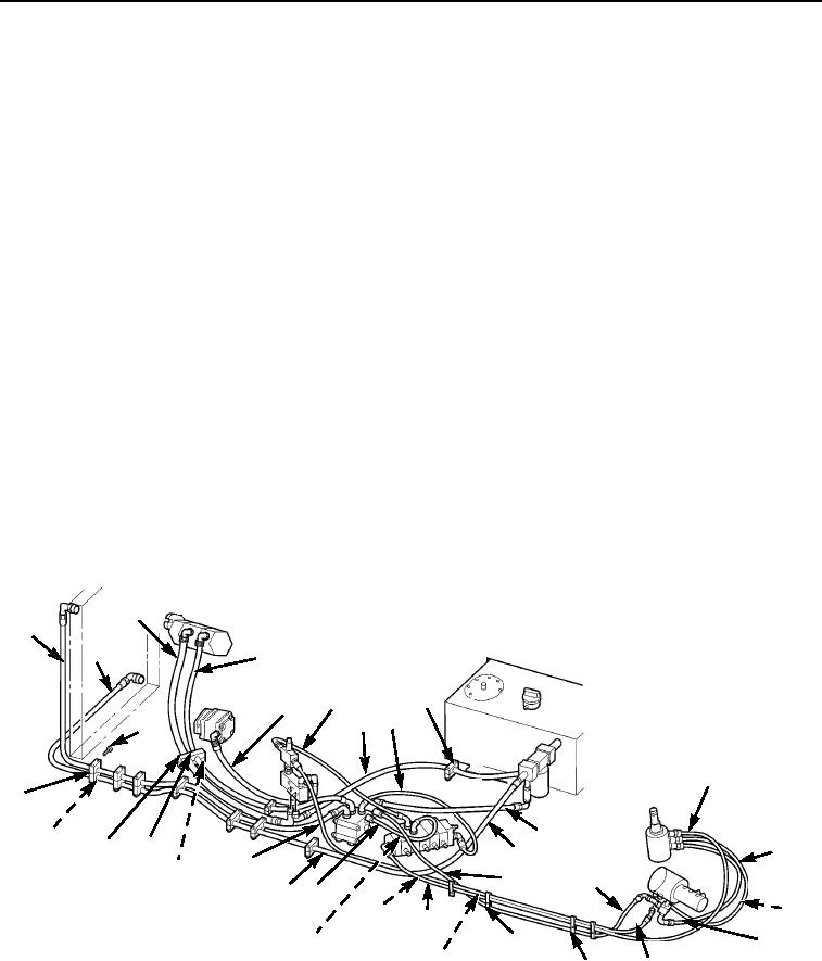
Install hoses (Figure 2, Items 12, 13, and 15) and six clamps (Figure 2, Item 14) to steering control unit.
2.
Connect hoses (Figure 2, Items 13 and 15) to pressure valve on booster valve.
3.
Install hoses (Figure 2, Items 11 and 16), three clamps (Figure 2, Item 17), and three clamps
(Figure 2, Item 14) to pressure valve.
4.
Install hoses (Figure 2, Items 2, 7, and 10) and clamp (Figure 2, Item 9) to return filter.
5.
Connect hose (Figure 2, Item 12) to valve bank.
6.
Install hoses (Figure 2, Items 6, 8, and 19) and tiedown strap (Figure 2, Item 18) to valve bank.
7.
Connect hoses (Figure 2, Items 8, 10, 11 and 19) to winch control valve.
8.
Install hoses (Figure 2, Items 1 and 4) to winch control valve.
9.
Connect hoses (Figure 2, Items 6, 7, and 16) to flow divider and steering valve.
10.
Install hoses (Figure 2, Items 3 and 5) to steering valve.
11.
Install two plate covers (Figure 2, Item 20), two cushions (Figure 2, Item 21), and four capscrews
(Figure 2, Item 22) to hoses (Figure 2, Items 3 and 4).
12.
Connect hoses (Figure 2, Items 3, 4, and 5) to main hydraulic pump and ground driven steering pump.
13.
Install seven cover plates (Figure 2, Item 23), seven half clamps (Figure 2, Item 24), and 14 capscrews
(Figure 2, Item 25) to hoses (Figure 2, Items 1 and 2).
14.
Connect hoses (Figure 2, Items 1 and 2) to oil cooler.
15.
Close dipstick cap.
3
1
2
4
9
6
5
8
7
25
12
24
10
23
21
22
13
2
16
20
11
11
14 19
14
14
12
18
15
17
14
16
14
M0110105
Figure 2. Return and Pressure Hydraulics Installation.
END OF TASK
03/15/2011Rel(1.8)root(maintwp)wpno(M00159)

