
TM 5-3810-305-23
0145
INSTALLATION - Continued
3.
Install and tighten axle lockout valve mounting nuts (Figure 6, Item 3).
4.
Install three washers (Figure 6, Item 1) and three capscrews (Figure 6, Item 2) through frame and into bottom
of manifold (Figure 6, Item 4).
5.
Connect electrical connectors (Figure 6, Item 3) to bottom of manifold (Figure 6, Item 4).
1
2
2
3
3
4
7
4
5
5
14
6
13
6
7
12
9
8
11 10
11
10
16
9
15
17
8
18
19
15
20
M2111105
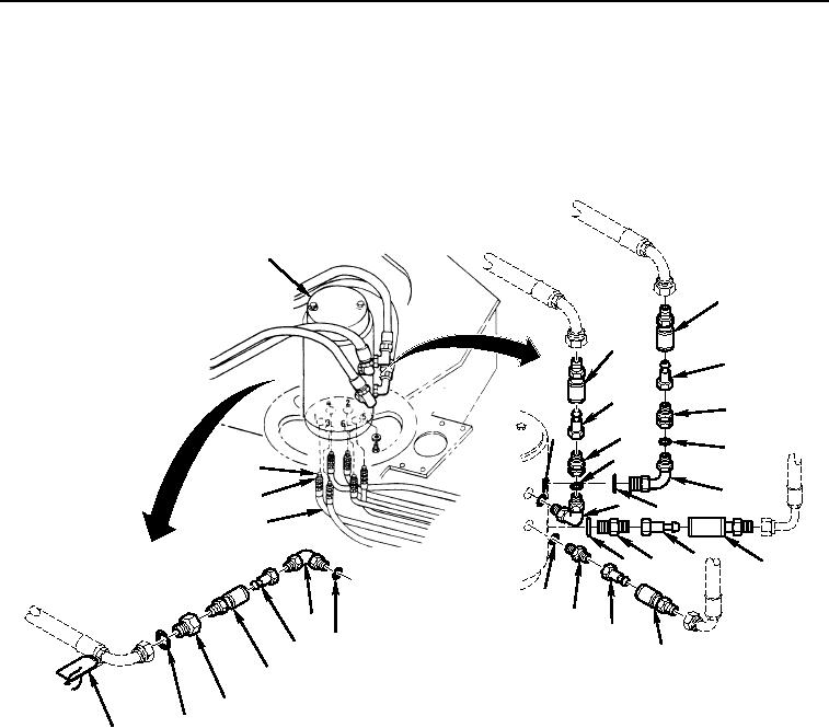
Figure 6. Rotary Manifold Quick Disconnects (Type II) Installation.
03/15/2011Rel(1.8)root(maintwp)wpno(M00162)