
TM 5-3810-305-23
0154
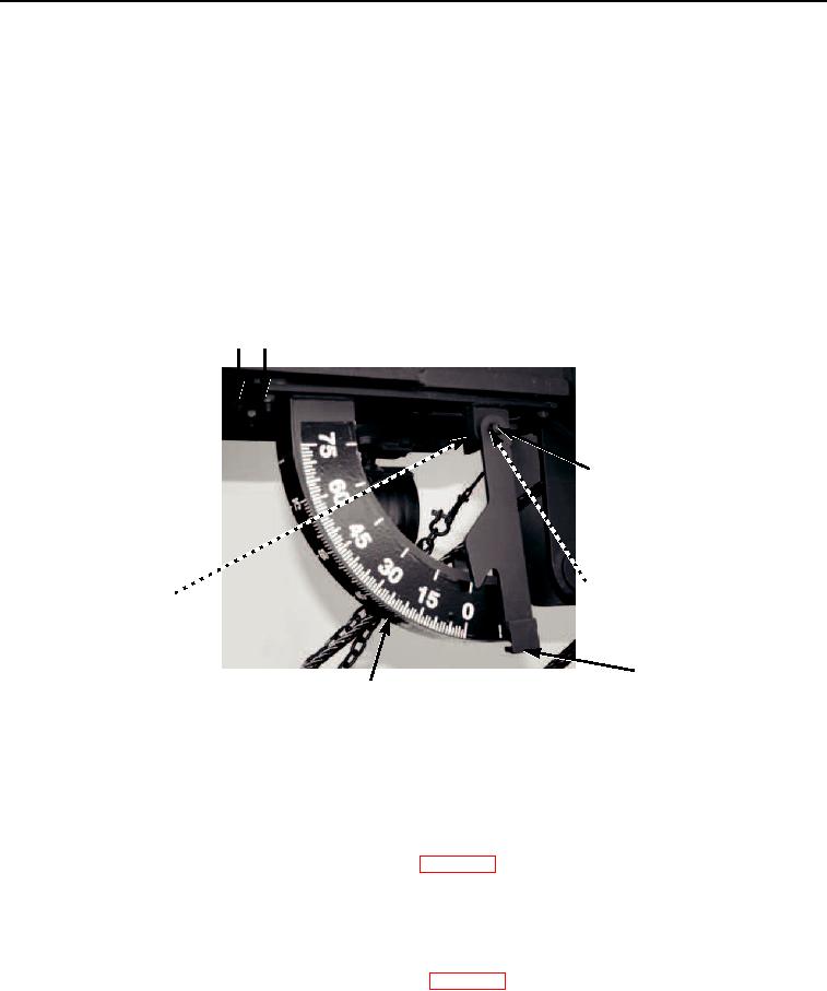
REMOVAL
1.
Remove locknut (Figure 1, Item 3), pendulum (Item 1, Figure 5), and spacer (Figure 1, Item 4) from bracket
(Figure 1, Item 6). Discard locknut.
NOTE
Do not remove cam follower unless damaged.
2.
Inspect cam follower (Figure 1, Item 7), if damaged, remove and replace.
3.
If necessary, remove cam follower (Figure 1, Item 7) by pressing it out of bracket (Figure 1, Item 6).
4.
Remove four locknuts (Figure 1, Item 2), bracket (Figure 1, Item 6), and strip (Figure 1, Item 1) from boom.
Discard locknuts.
1
2
3
4
7
5
6
M0595105
Figure 1. Boom Angle Indicator Removal.
END OF TASK
CLEANING
Clean parts IAW General Maintenance Instructions (WP 0162).
END OF TASK
INSPECTION
Inspect parts IAW General Maintenance Instructions (WP 0162).
END OF TASK
03/15/2011Rel(1.8)root(maintwp)wpno(M00170)