TM 5-3810-307-24-1-1
SHIFT CONTROL ASSEMBLY (CARRIER CAB)
Removal
a.
Ensure battery disconnect is in OFF position.
b.
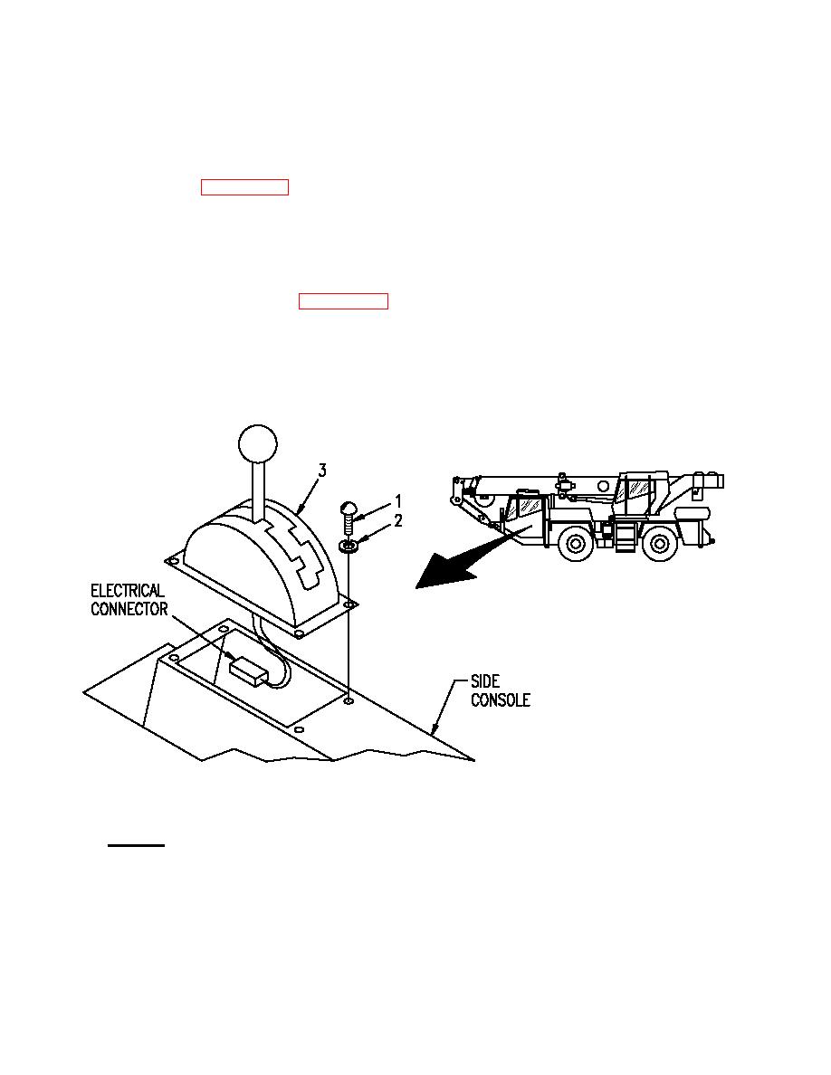
Remove screws (1, Figure 2-1-18) and lockwashers (2) securing shift control assembly (3) in side console.
c.
Lift shift control assembly (3), disconnect electrical connector, and remove shift control assembly from side
console.
Installation
a.
Position shift control assembly (3, Figure 2-1-18) near side console and connect electrical connector.
b.
Lower shift control assembly (3) into side console and secure with lockwashers (2) and screws (1).
LEGEND
1. Screw
2. Lockwasher
3. Shift control assembly
2-1-86


