TM 5-3810-207-20/TO 36C23-3-37-12
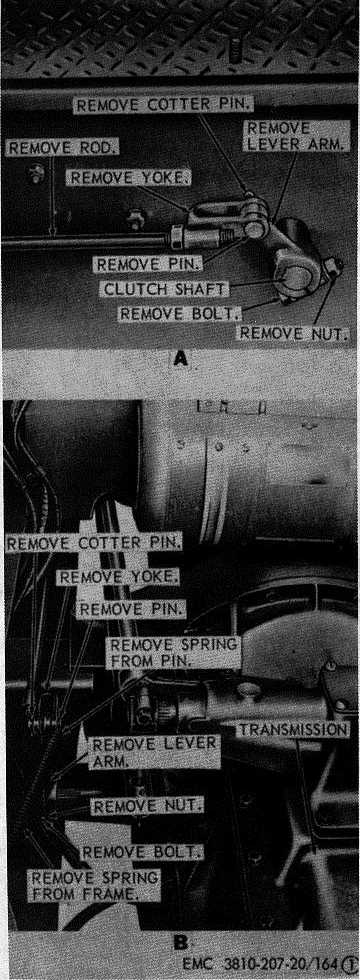
A-Clutch linkage control rod
B-Clutch lever arm and spring
Figure 164. Clutch adjustment and linkage assembly,
removal, installation, and adjustment.
(2)
Install the floorboard in the cab (par. 319).
d.
Adjustment.
(1)
Measure dimensions "A" (C, fig. 164).
(2)
If adjustment is needed, add or remove
shims to obtain 1 3/16 inch minimum
measurement or 1 1/4 inch maximum
measurement as instructed on D, figure
164.
(3)
Adjust linkage (TM 5-810-207-10) to obtain
the 1/8 inch clearance shown on C, figure
164.
269. Clutch Pedal and Cross-Shaft
a.
Removal.
(1)
Remove the clutch linkage from the cross-
shaft (par. 268).
(2)
Remove the clutch pedal and cross-shaft in
the numerical sequence as instructed on
figure 165.
b.
Cleaning, Inspection, and Repair.
(1)
Clean all parts with an approved cleaning
solvent.
(2)
Inspect the cross-shaft and bushings for
straightness or excessive wear. Replace a
defective cross-shaft.
(3)
Repair or replace damaged parts as
necessary.
c.
Installation.
(1)
Install the clutch pedal and cross-shaft in
the reverse of the numerical sequence as
illustrated on figure 165.
(2)
Install the clutch linkage on the cross-shaft
(par. 268).
214