TM 5-3810-207-20/TO 36C23-3-37-12
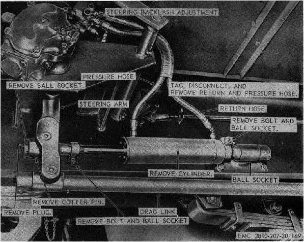
Figure 169. Carrier hydraulic cylinder, removal and installation.
c.
Installation.
(1)
Install the steering wheel as illustrated
on figure 170.
(2)
Install the horn button assembly (par.
226).
279.
Drag Link
a.
Removal. Remove the drag link assembly as
instructed on figure 171.
b.
Cleaning and Inspection.
(1)
Clean all parts with an approved
cleaning solvent.
(2)
Inspect all parts for bends, breaks,
excessive wear, and other damage.
Replace defective parts as necessary.
c.
Installation. Install the drag link assembly as
illustrated on figure 171.
280.
Steering Arm
a.
Removal.
(1)
Remove the hydraulic cylinder (par.
276).
(2)
Remove the drag link (par. 279).
(3)
Remove the steering arm as instructed
on figure 172.
b.
Cleaning and Inspection.
(1)
Clean all parts with an approved
cleaning solvent.
(2)
Inspect all parts for breaks, cracks, or
other damage. Replace defective parts
as necessary.
222