TM 5-3810-289-34
1. Use ST-605 Mandrel and Block in an
arbor press to press out old piston pin bushing. Figure
2. Use a straight or tapered sleeve from ST-
605 depending upon type of connecting rod.
3. Aline oil hole and use ST-605 Mandrel to
press in new bushings to a point flush with milled side
surfaces.
4. Aline tapered bushing half on tapered
sleeve and press flush with milled side surface. Turn rod
over to install second bushing.
5. Fill lubrication holes with soap to keep
shavings out.
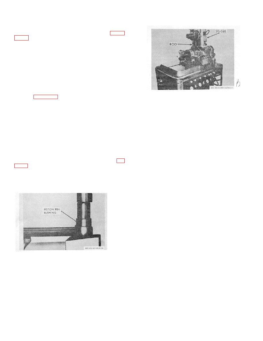
6. Mount connecting rod in ST-526 Boring
Figure 3-209. Boring piston pin bushing on ST-526.
Machine, figure 3-209.
7. See instruction booklet furnished with the
groove, removing as small amount of material as
machine for operating procedures.
possible.
8. Check rebushed rods in ST-561 as
(c) The tool is a formed tool so balance of
described in previous paragraphs.
cut will come from top of groove.
9. When reworking wide connecting rods for
(d) Hold machined surfaces within 0.0015
use with new pistons:
in. total indicated runout.
(a) Machine piston pin end of connecting
Caution: Limits must be held accurately for
rod an equal amount on both sides until it measures
satisfactory ring performance.
1.150/1.160 in. wide.
(e) Stand letters "OW" (over-width ring) after
(b)
Chamber pin hole 15 degrees by
part number on piston crown.
0.200/0.040 in. deep to allow installation of bushing.
d.
Assembly.
Piston-to-Connecting Rod
(c) Install bushings.
Assembly.
(d) Bore new bushing to 1.500/1.5 in. (4, fig.
(1) Pistons are machined to a very close
weight tolerance; therefore, as long as the same part
(e) Use ST-561 to check rebushed rods.
number piston is used throughout the engine weight
(2) Pistons.
does not affect engine operation.
Note. This applies only to aluminum pistons
Note. Be sure rod and cap are stamped before
without top ring groove inserts. Observe following
disassembly to prevent mixing parts.
precautions when regrooving.
(2) Connecting rods have the weight (720,
etc.) stamped on the rod cap and must be matched with
other rods by weight.
Total weight between rod
assemblies in any one engine should not vary more than
0.03 lb. Weight includes piston pin bushing, bolts,
lockplates and bearing shells.
(3) Install one piston pin snap ring in piston
pin bore.
(4) Heat aluminum pistons in boiling water
or, not exceeding water boil temperature, in an oven and
install pin through piston and connecting rod pin bores
before piston cools; at 70 o F. the pin fit is 0.0001 to -
0.0003 in. which prevents pin assembly unless piston is
Figure 3-208. Piston pin bushing installation.
heated.
Caution: Never drive piston pins in pistons.
(a) Set up piston in lathe or similar device.
Driving may cause distortion of the piston, causing
Make certain piston is held securely without dam aging
piston seizure in the cylinder liner.
or distorting machined surfaces. Install ST 483 (15
(5) Secure pin with second snap ring at
degree grooves) Grooving Tool in lathe.
opposite end-of pin bore.
(b) Set tool to only clean up bottom face of
e. Installation.
(1) Check all pistons (for any one engine) to
make sure they are the same part number.
(2) Check all connecting rods and caps to
be cer-
3-74


