TM 5-3810-289-34
(c)
Advance each nut one-half hex (30
degrees).
(d) Finish tightening by advancing each nut
an additional one-half hex (30 degrees).
(e) Check torque in clockwise direction; if
less than 38 ft lbs. is required to turn nut after tightening
sequence is completed, remove U-bolt(s) and replace
with new one(s).
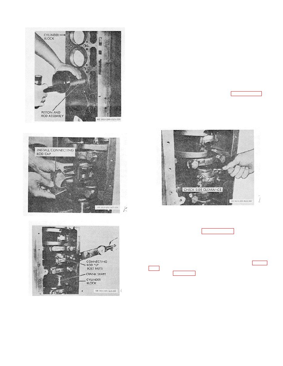
(22) Tightened rod should be free to move
sideways on crankshaft journal.
Check with hand
pressure first; tap lightly with soft hammer only if
necessary. Check side clearance (between crankshaft
journal and side of connecting rod), figure 3-215; a
minimum of 0.008 in. clearance should be present in
this area.
Note. If rod is not free, remove cap and check for
improper bearing shell size, bur, dirt, tang
misengagement, etc. before proceeding with engine
assembly.
Figure 3-212. Piston and rod assemblies installation.
Figure 3-215. Rod-to-crankshaft side clearance check.
Figure 3-213. Connecting rod cap installation.
3-44. Crankshaft Assembly; Bearings; Seals
a. Removal.
(1) Refer to paragraph 3-43 and remove the
connecting rods.
(2) Turn engine so bottom side is up; loosen
capscrews securing caps to block, leaving two or three
threads engaged in block to pilot caps as they are
removed.
(3) Pry each cap loose with pry bar (fig. 3-
from block (fig. 3-217).
Note. Lower thrust rings are held in place with
dowels on No. 7 main bearing cap. Upper thrust rings
rest in chamfer on No. 7 main bearing bore in block. Be
careful not to drop thrust rings; remove before lifting
Figure 3-214. Torquing connecting rod U-bolt nuts.
crankshaft.
assembly in foregoing manner; then:
(4)
Remove main bearing shells from
(a) Tighten each nut (first front, then rear) to
crankshaft (if they did not adhere to caps).
30 ft. lbs.
(b) Loosen all nuts and repeat steps 19 and
21a.
3-76


