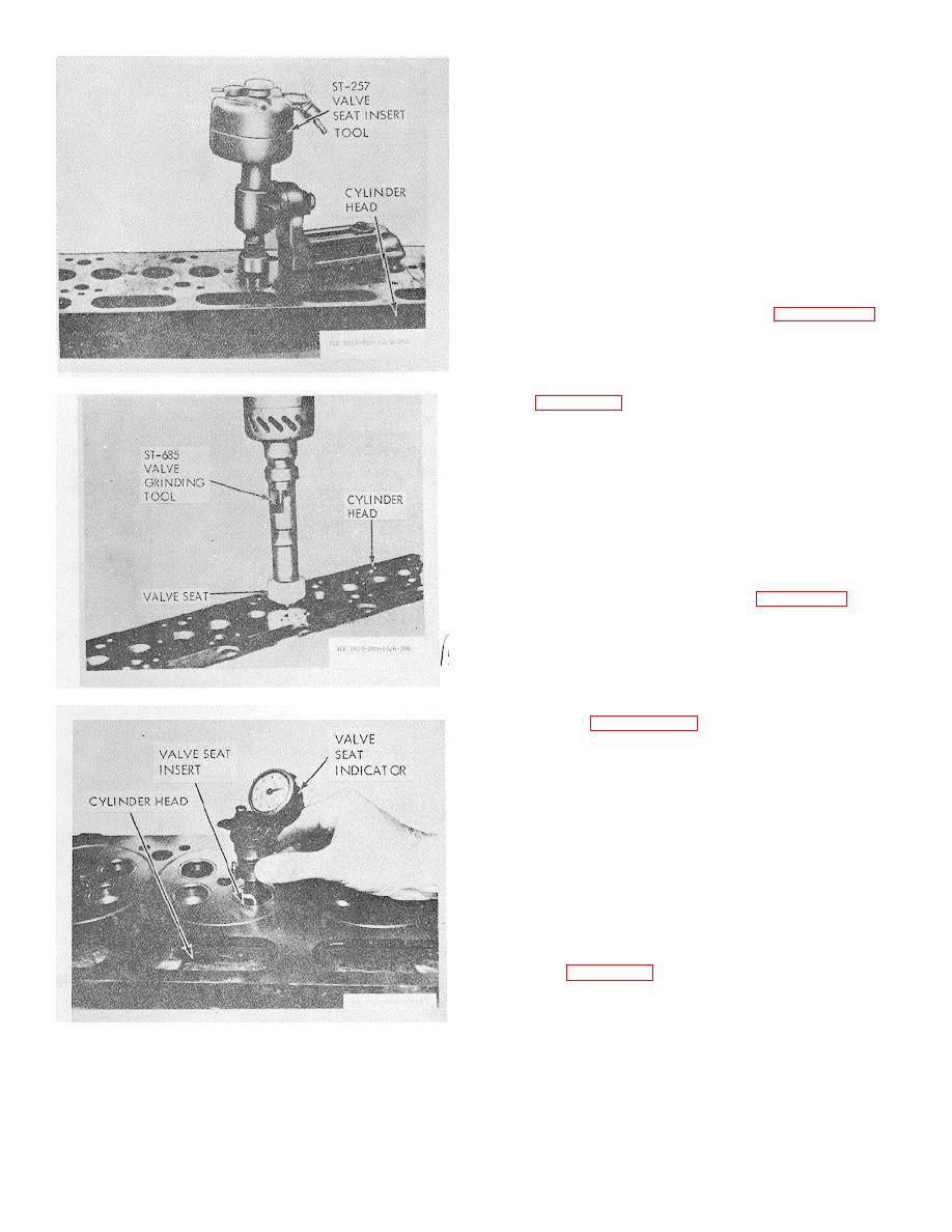
(4) Grind valve seats as follows: (a) Use
ST-685 Valve Grinding Machine or machine of equal
standard.
(b) Check condition of grinding
equipment.
1. Mandrels must be straight and
of proper size to fit in guides.
2. Bushings in grinder must be
clean and must fit improperly in guide mandrel.
3. Drive unit bearings must be in
good condition.
(c) Dress stone to 30 degrees from
horizontal.
(d) Grind valve seats, holding seating
motor as nearly vertical as possible, figure 3-257. A
severe angle will cause seat to be out-of-true depending
upon amount of wear in grinder bearings, mandrel,
bushings, etc., even though grinder has a universal joint.
iCheck valve seat width which should be 1/16 to 1/8 inch.
Figure 3-256. Coutnterbore for valve seat insert.
See figure 3-258.
1. If seating area is wider than
1/8 inch maximum, stock can be removed with specially
dressed valve seat grinder stones.
2. Narrowing should not extend
beyond chamfer on seat insert. Chamfer provides for
peen metal.
(f) Dress wheel for final finish.
(g) Finish grind with light touches of
stone against face.
(h) Check valve seat concentricity
with valve seat indicator as shown in figure 3-258.
1. Use valve guide as a center.
2.
Total run out should not
exceed 0.002 in.
3. The gage must be a perfect fit
on pilot mandrel.
Figure 3-257. Refacing valve seat.
(i) Check seat with mating valve as
described in paragraph 3-31 to insure proper sealing.
e. Installation. Install valve seat and peen
around insert in at least 4 or 5 places with the peening
tool available as extra equipment in ST-257. A A/ inch
diameter round end punch may also be used.
3-47. alve Crossheads and Guides Replacement
Caution: Over-swagging around insert may
crack cylinder head.
a. General Valve crossheads are used on
engines with dual intake and exhaust valves to insure
that both valves under the crosshead are opened and
closed at the same time.
b. Remova.
(1) Lift valve crossheads from crosshead
guides, figure 3-259. In some cases these may be left
in cylinder head and the complete unit sent to the head
repair section.
(2) Remove crosshead guides to be
Figure 3-258. Indicating valve seat insert.
replaced,
3-91


