TM 5-3810-294-34
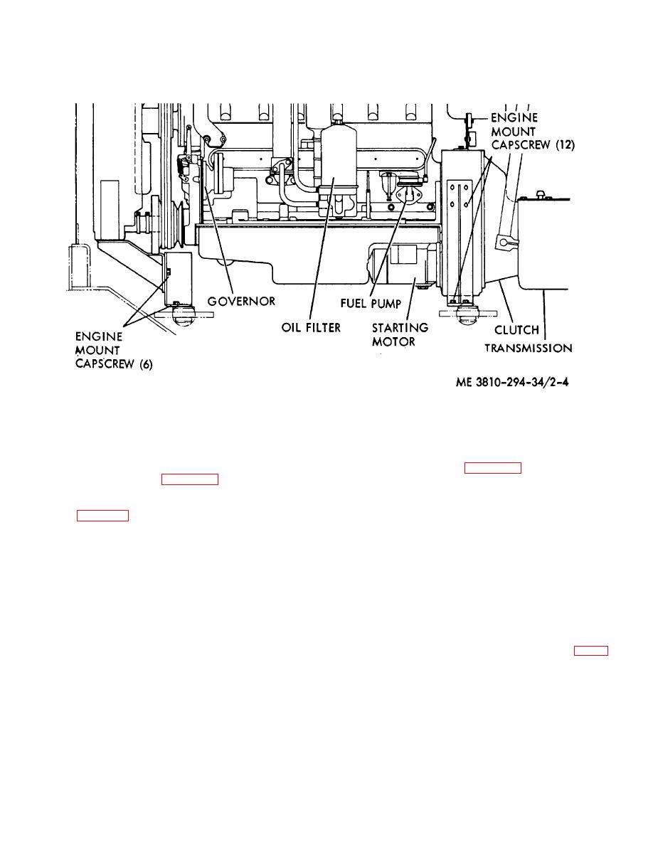
Figure 2-4. Engine mount capscrews, removal and replacement.
c.
Installation.
(4) Refer to figure 2-3 and connect the
(1) Refer to figure 2-3, attach a suitable
operator's clutch lever linkage to the clutch lever.
lifting device and place the engine and transmission
(5) Carefully inspect the engine. Make
assembly on mounting brackets of the revolving frame.
sure all hoses, pipes, tubes, and electrical connections
Refer to figure 2-4 and install mounting capscrews.
are proper and secure.
Service engine and
(2)
Refer to TM 5-3810-294-20 and
transmission as instructed in TM 5-3810-294-20 before
perform the following operations:
returning the machine to operation.
(a) Connect tachometer drive cable at
2-14. Transmission / Clutch Assembly
the engine. Connect fuel tubing to the engine at the fuel
a. General. The transmission / clutch assembly
pump and intake manifold.
is removed from the crane as a unit, along with the
(b) Connect all electrical wiring
engine. The following procedures are for removing the
disconnected during removal.
transmission and clutch from the engine, after the
(c) Install propeller shaft.
engine has been removed.
b. Removal.
standpipe.
(1) Place the engine and transmission /
(3) Install gantry (FIG. 2-2).
clutch assembly on a suitable stand as shown in figure
2-5.
2-22


