
22. Install converter pressure regulator
valve, spring, gasket and plug in pump
cover (see Figure 4C-28 on page 4C-24).
23. I n s t a l l p l u g s ( 2 8 , 2 9 , 3 0 a n d 3 1 ,
INPUT DISCONNECT CLUTCH. To re-
build the disconnect clutch, proceed as
follows (see Figure 4C-34 on page
4C-26):
1. Using a bearing puller, remove ball
bearing assembly (51) from the end of
the converter drive shaft.
2. Remove four bolts (32) and lock wash-
ers (33) securing access cover (34).
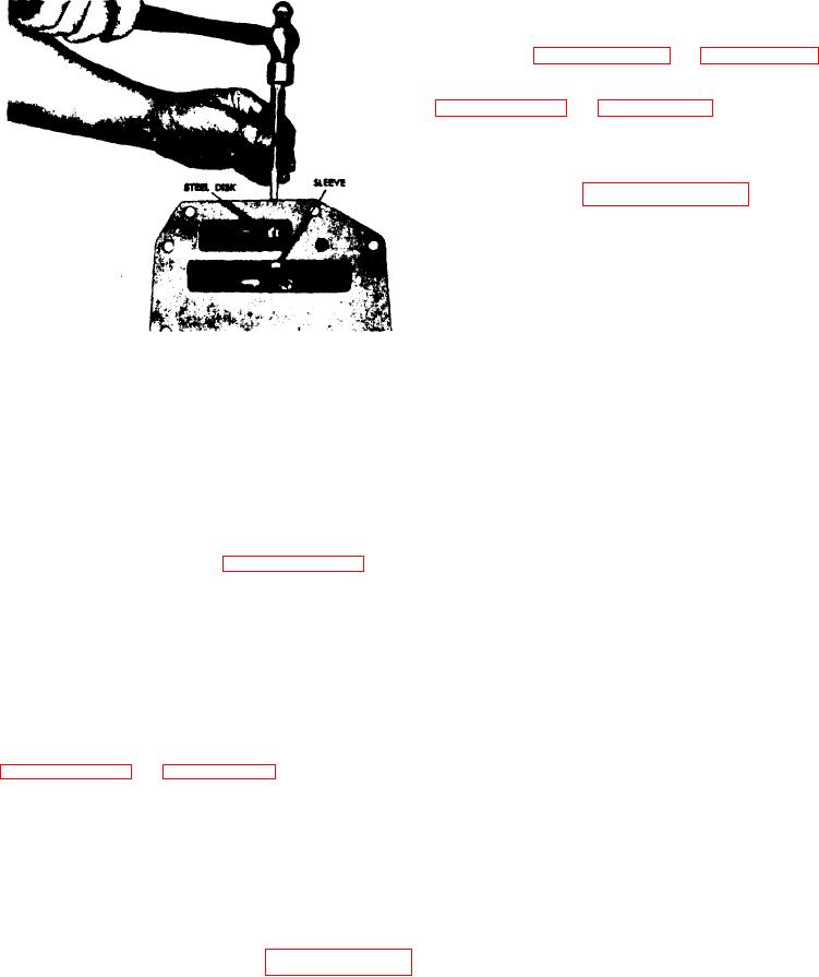
Figure 4C-33. Removing Oil Pump
B e a r i n g Sleeve
3. Disconnect the two grease fittings (25
and 36) and nuts (26 and 37) from the
Install the seal ring, flush to 0.020 to
bearing lube tubes (27 and 38). Remove
0.030 inch (0.508 to 0.762 mm) below the
access cover (34).
edge of the bearing bore.
4. Using wrench TSD 20231, remove
15. Install the hook type seal ring onto
spanner lock nut (1) from the front end
the pump drive shaft.
of the converter drive shaft.
16. install oil pump driving gear and
5. Using caution not to damage the bear-
while holding it in position, install the
ing diameter, drive or press converter
driving gear shaft (see Figure 4C-31).
drive shaft (4, Figure 4C-40 on page
4C-35) rearward out of clutch assembly
17. If needle roller bearing was removed
(4) and ball bearing (35). Remove con-
from the pump driven gear, install new
verter drive housing assembly (7,
replacement. Install bearing, pressing
Figure 4C-40 on page 4C-35), but DO
on the numbered end of the bearing cage
NOT disassemble the drive shaft from
and into the chamfered end of the gear,
the drive housing, since it was partially
flush with the bottom of the chamfer in
machined after assembly.
the gear.
6. Remove key (2), clutch assembly (4)
18. Install the assembled gear and bear-
and attached bearing lube tube (27).
ing
into
the
oil
pump
body
(see
7. If necessary for parts replacement,
remove elbow (28) and bearing lube tube
(27) from shift collar (18).
19. If the needle roller bearing was re-
moved from the oil pump body cover, in-
8. Remove eight b o l t s ( 4 0 ) a n d l o c k
stall new replacement. Install the
bearing, pressing on the numbered end
washers (41) from bearing retainer (39).
of bearing cage, until the bearing is
firmly seated in the pump cover.
9. Remove bearing retainer (39) and at-
tached bearing lube tube (38).
20. Install the clutch pressure regulator
10. Remove ball bearing (35) from clutch
valve spring, valve and snap ring in the
housing (30).
oil pump body cover (see Figure 4C-29
on page 4C-24).
11. Remove bearing lube tube (38) from
bearing retainer (39).
21. Install the oil pump body cover gas-
ket and assembled cover onto the oil
12. Loosen two bolts (47) and lock wash-
pump body and secure with six bolts and
ers (48) in clutch shifter yoke.
lock washers.
Transmissions