
Figure 4C-25. Installing Stator
Figure 4C-26. Spring and Rollers in
Springs and Rollers
S t a t o r Cam
7. Install retainer (16) in sprag race
11. Install snap ring (14).
(17).
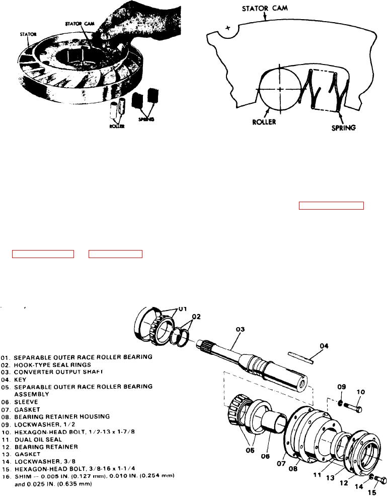
OUTPUT SHAFT AND BEARING RE-
8. Install bearing assembly (15) in sprag
TAINER. To rebuild the output shaft,
proceed as follows (see Figure 4C-27):
race (17). Press the bearing until it is
firmly seated against the retainer in the
race.
1. Remove two hook type seal rings (2)
from output shaft (3).
9. Install sprag clutch assembly (18),
2. When it is necessary to replace roller
flange side out, onto converter turbine
bearing assemblies (1) and (5), support
(1, Figure 4C-39 on page 4C-34).
the shaft and bearing assembly, small
10. Install the bearing with the race and
end up, on two steel plates in an arbor
retainer onto the turbine assembly.
press. The plates must be placed be-
tween the two bearings, making certain
Press the bearing until it is firmly seated
that only the inner race of the bearing
against the shoulder on the turbine as-
sembly.
F i g u r e 4C-27. Exploded View of Output Shaft and Flange