
TM 5-3810-305-23
0024
INSTALLATION - Continued
6.
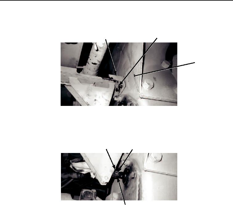
Install four bolts (Figure 26, Item 2) to shift bracket (Figure 26, Item 1) and transmission (Figure 26, Item 3).
2
1
3
M0067105
Figure 26.
Power Pack Installation.
7.
Install new cotter pin (Figure 27, Item 1) and straight pin (Figure 27, Item 2) to transmission shift
control (Figure 27, Item 3).
1
2
3
M0068105
Figure 27.
Power Pack Installation.
03/15/2011Rel(1.8)root(maintwp)wpno(M00029)